
Ahhh, where it all started.
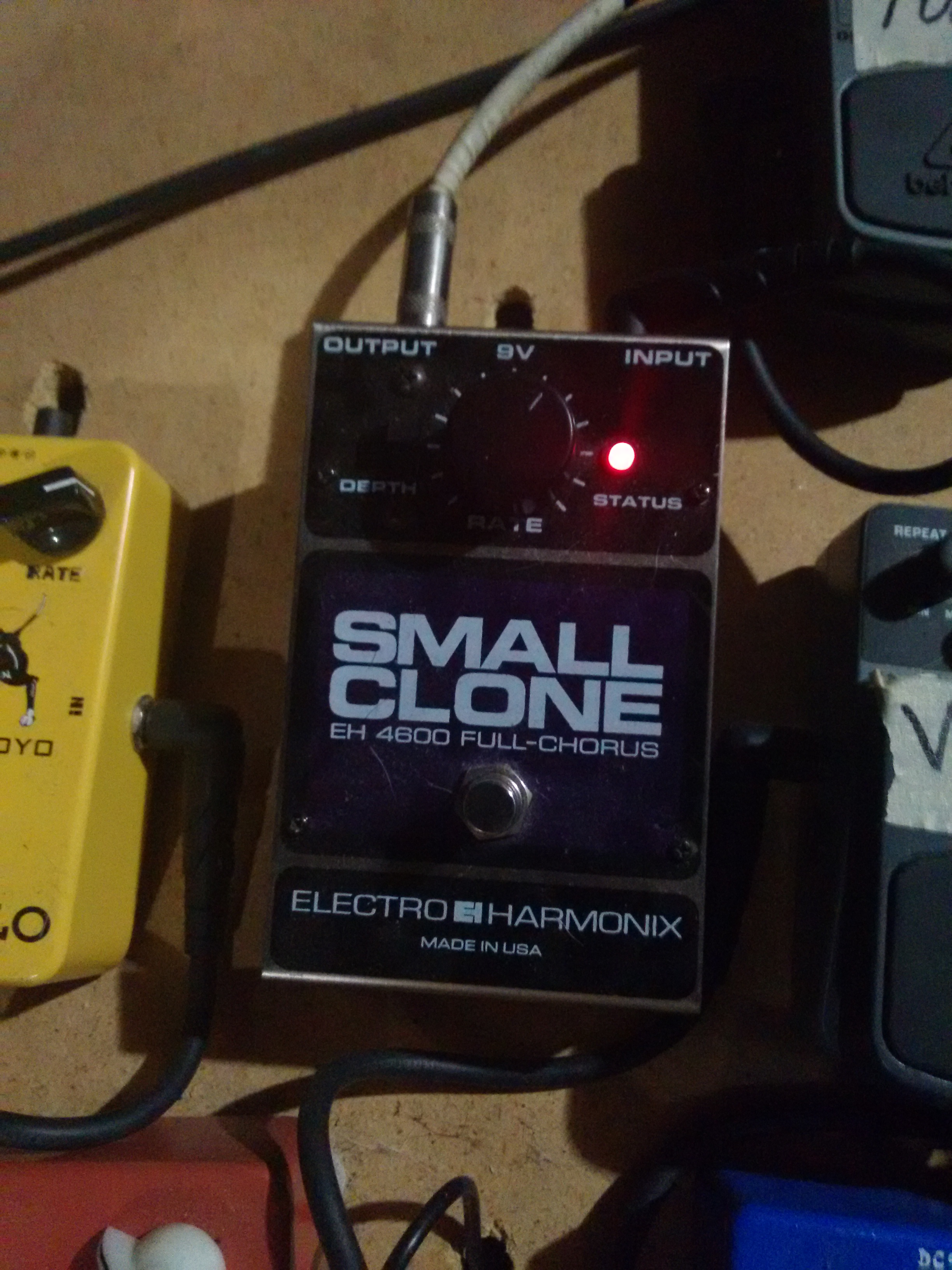
I was jamming with a friend in his basement and he had a bunch of pedals, which I was noodling around with. None really stuck out to me until this little guy. If you want a sample of what it sounds like, there are plenty of test drives on YouTube. You may recognize its sound from Nirvana songs (only 90s kids will myeh myeh myeeehhh).
I immediately fell in love with it. It has such a distinctive sound, dark and warbly. I always describe it as “watery”, though that doesn’t seem to make sense to anyone else. Anyway, at this point I hadn’t made any pedals, but once I got into it, this was the one that was always on my mind. I had made several, but I wanted this one to be my best yet.
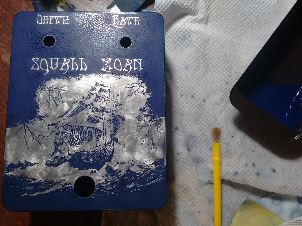
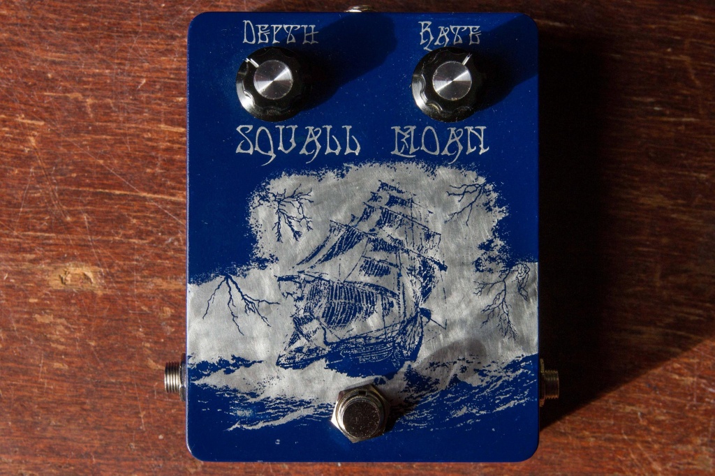
So far I had pedals of a few colors, but none in blue yet. I wanted the theme to be something a little dark and…watery. I decided on this, which really came together when I found the font on one of those free font sites:
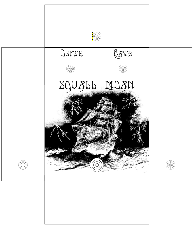
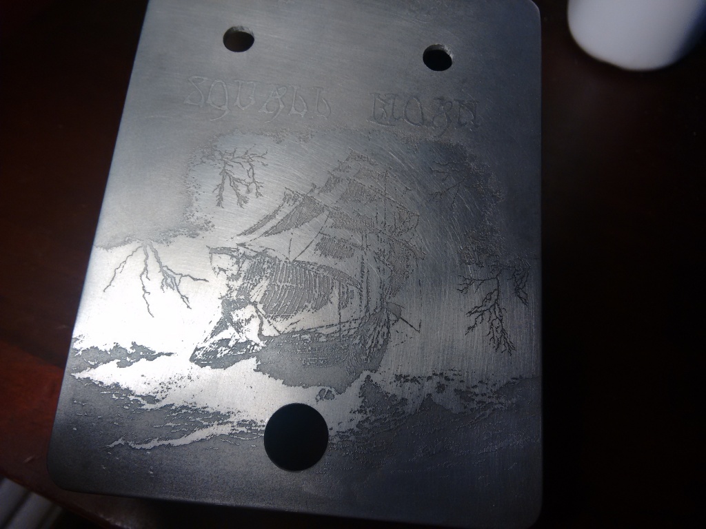
You can see the target circles, which are where I’ll be cutting the through holes for the pots at the end. The picture is a composite from a few things. The main part, the ship in the choppy waters, is one I chose from a ton of images when I googled image searched “stormy ship painting”. It’s apparently called “Cutty Sark Caught In A Squall”, by Eric Bellis:

I also added some simple images of lighting I got online, and used a few tools in GIMP to create the clouds. Now, we have to do the step where we transfer the toner to the metal, which will act as the resist for the etchant. We do this by ironing it on with an ordinary clothes iron, very thoroughly:
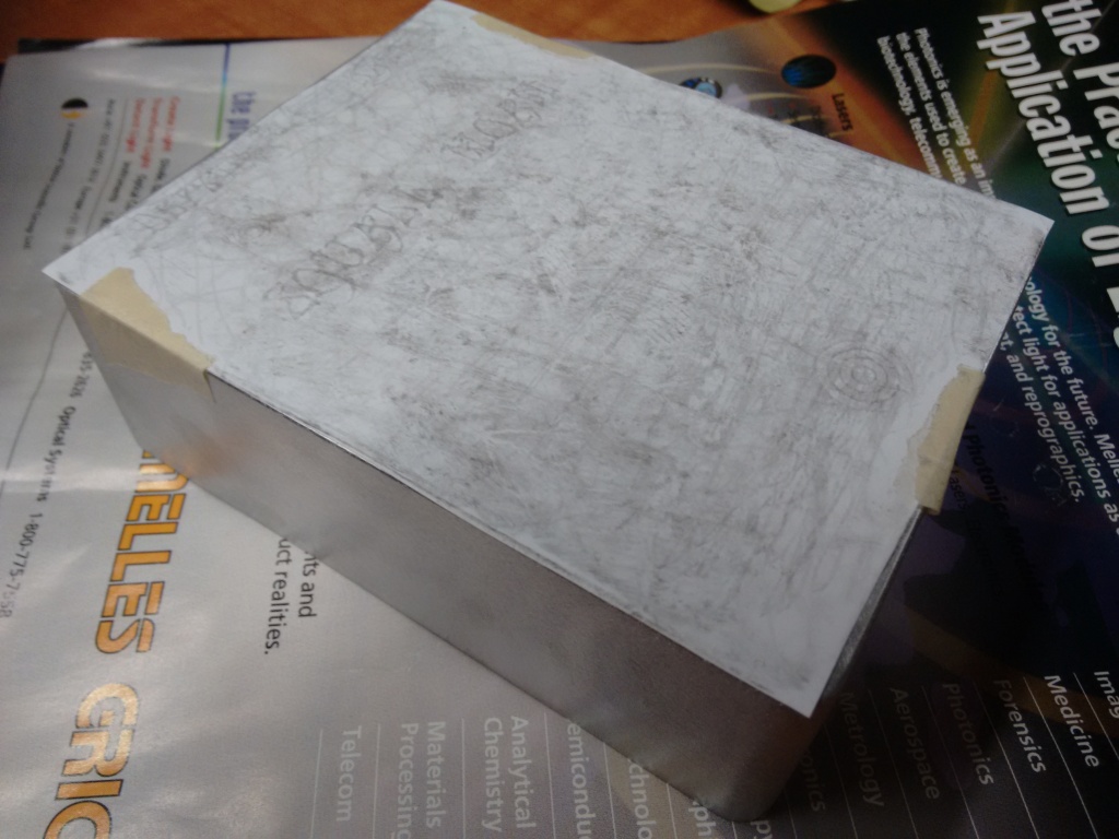
Then, we carefully peel off the paper and very carefully and gently scrub off any paper covering the metal (where we want it to etch). From there, we etch the metal, wash it off with water, and then remove the resist with acetone:
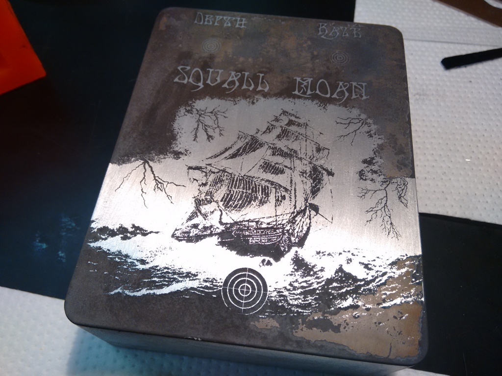
It always looks pretty cool straight out of the etch. I think it’s the fact that the black part (the aluminum oxide, I think) has a very “matte” look, and a small part of me is always tempted to keep it that way.
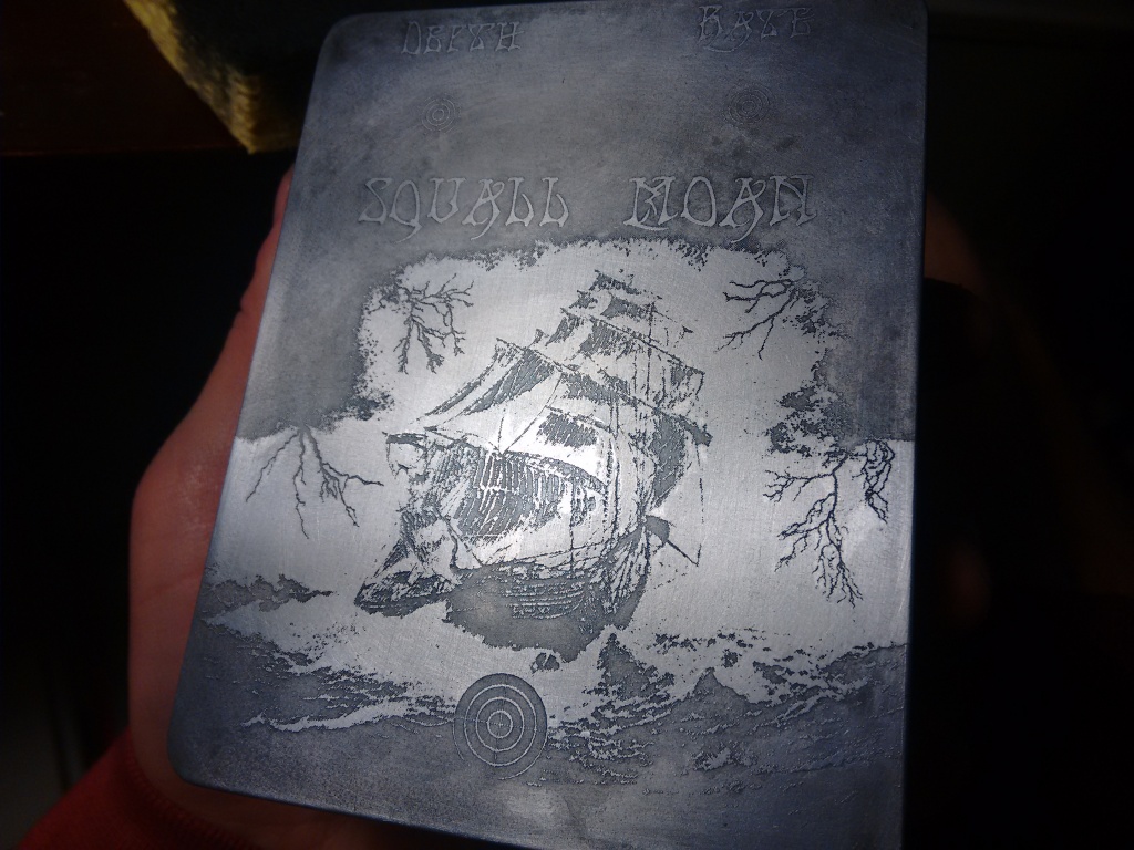
Next, we scrub the oxide off. In contrast to the other parts involving scrubbing, you can be pretty aggressive here because it’s just metal and we want the paint to only be directly on the metal. It also looks sweet at this point, but we’ve gotta keep going!
Next, the paint job. I don’t have a pic of it with all the paint still on unfortunately, but that looks kind of lame anyway. Here, I’ve begun to sand the paint off the areas that were “embossed” (i.e., not etched):
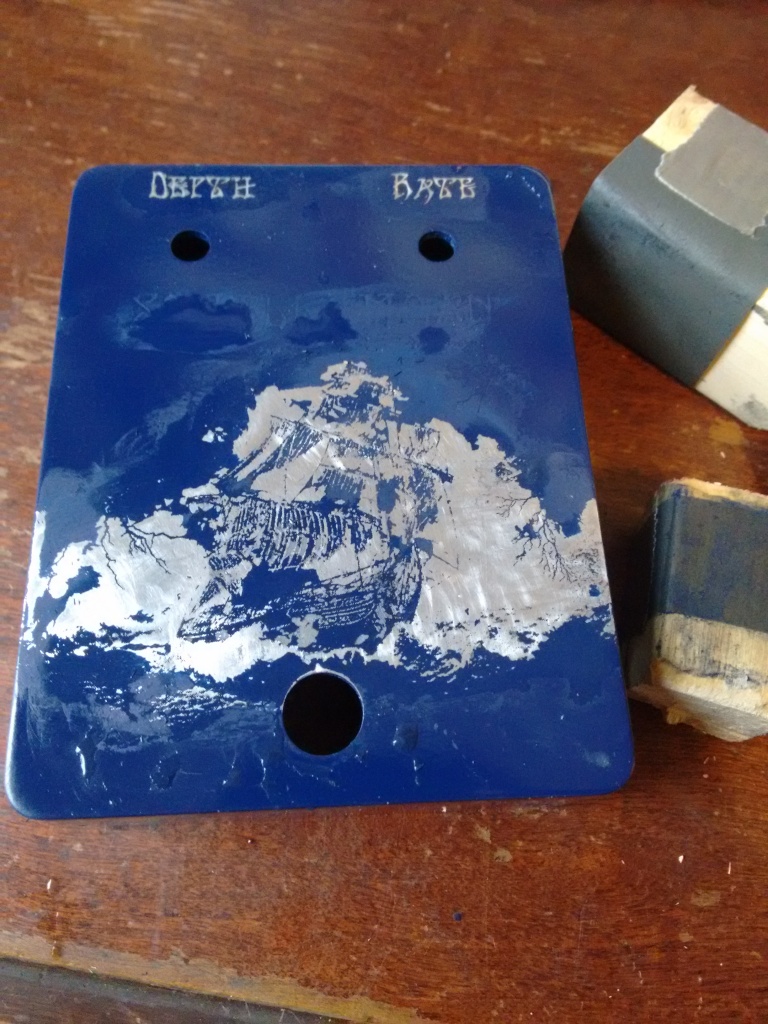
I had to be reeeaallll careful at this point. Some of the features were so small that putting a bit too much pressure while sanding could mess it up. So, you just use fine, fine sandpaper (800 grit I think) and go veerrryyy slow.
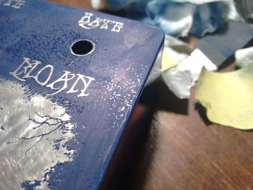
Notice that at this point, after sanding, a lot of the remaining paint looks… well, pretty crappy. It’s hard to sand the parts you need to without scuffing the paint at all, which causes it to immediately have a matte rather than shiny surface:
Don’t worry though! The final lacquer coat fixes all. Remember that time you peed yourself in front of your first grade class? Remember when you didn’t tell that person you loved them, and now it’s too late? Remember that time the waiter told you to enjoy your meal and you said “you too”?
LACQUER FIXES ALL.


Gaawwdddamn. Look at that detail.
So far, we’ve only been looking at the chassis, the outside. The surface. So shallow of us. But there is more!
In this case, because I wanted it to be extra nice, I didn’t put it together with stripboard or design the circuit board myself (oh god, never again). The source I used for the circuit was this Tonepad page, where they very helpfully give you the plans for free, with the option of buying the kit from them. The PDF they give you is really helpful, and even mentions a few mods you can do.
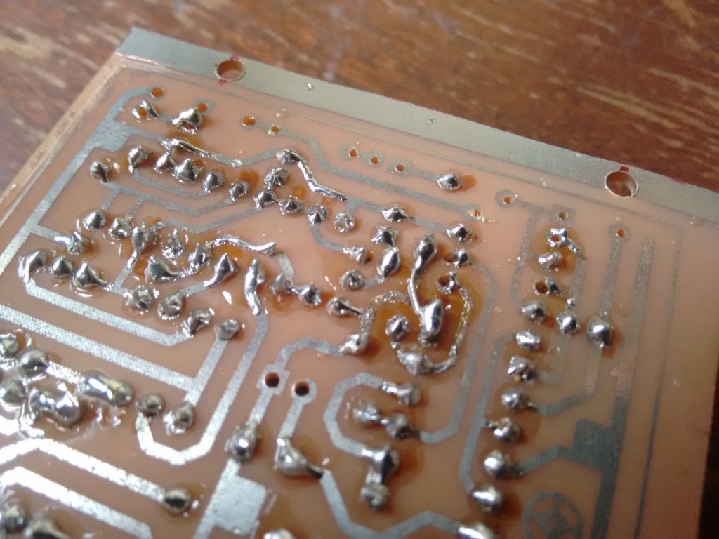
Yet, I still managed to mess up at first. If you notice in the photo below, the through-holes are different sizes. That’s because I was impatient, and broke the carbide drill bits of the right size. I broke…so many. Let us not speak of this again.
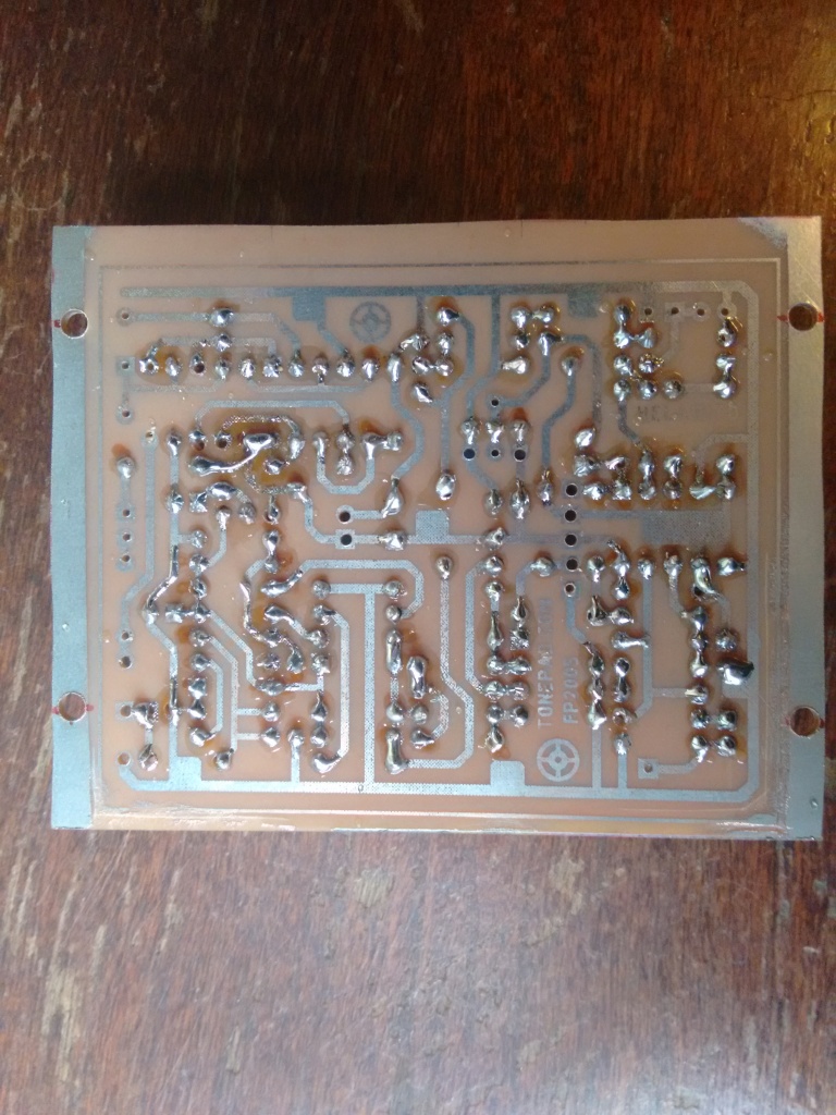
Jesus, that’s ugly.
ANYWAY, because I wanted to do this right, I re-etched and re-drilled a new PCB:
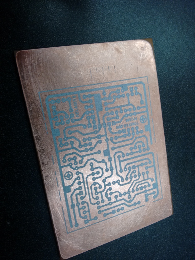
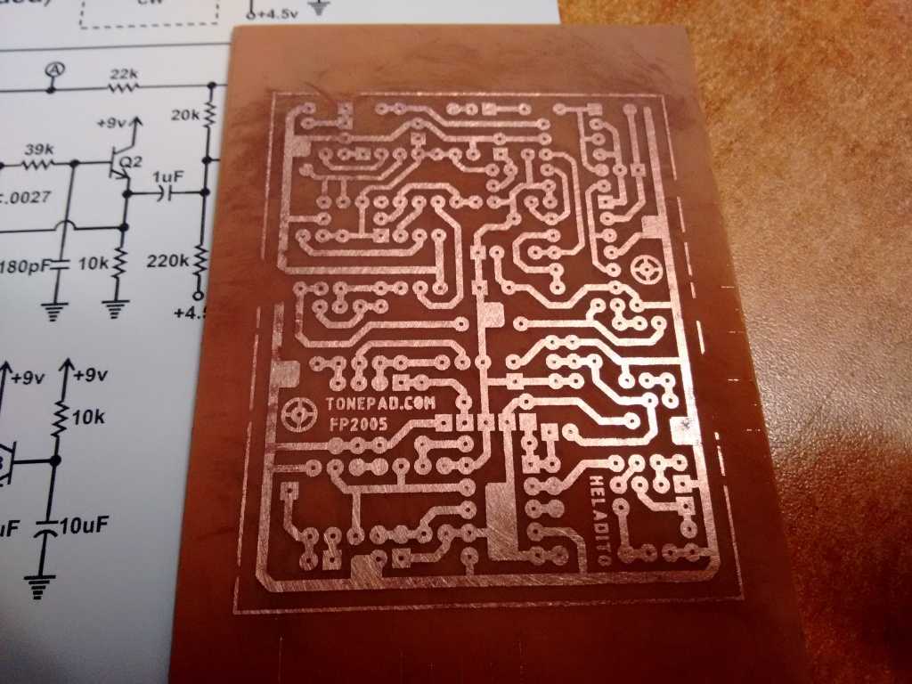
Ahhhhhh look at those clean traces and nice holes for the solder to wick to. Soldering the components in:
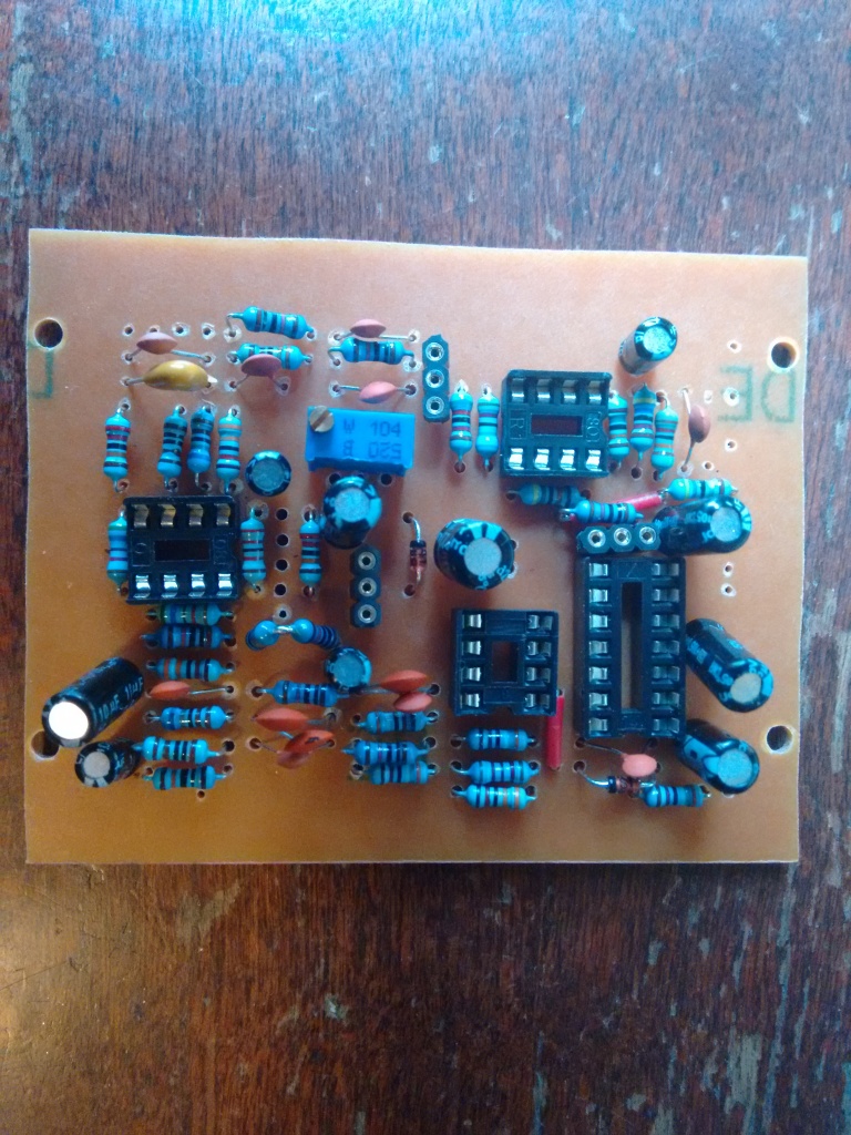
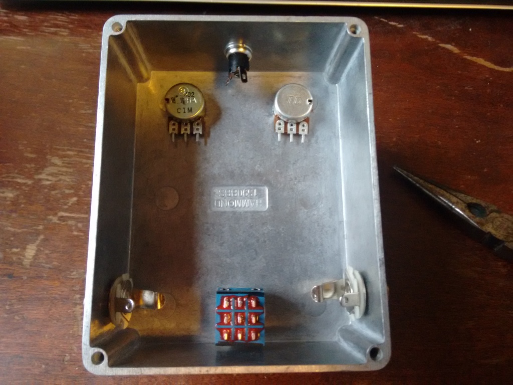
I add the ICs and transistors at the very end in their sockets. Inserting the pots, jacks, and stop button:
And wiring it all up!
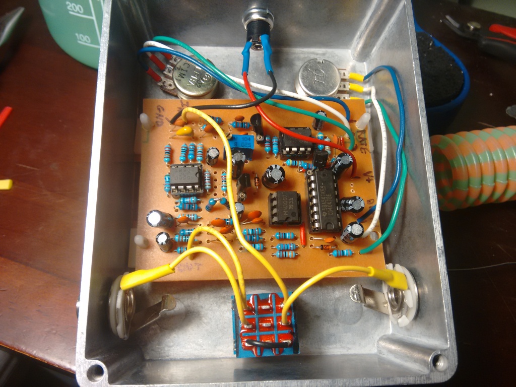
Notice that for this one, I used plastic standoffs, which you can see in the corners of the PCB, to prevent any electrical contact with the inside.
And, the fancy photo with it all put together!
I won’t say a ton about the circuit itself, but the two ICs that are doing most of the work are the CD4047 and the MN3007. The CD4047 is a multivibrator, which I think is just used for producing a square wave here. This is used to modulate the MN3007, which is a “bucket brigade device” (BBD), that basically uses a series of capacitors to delay a signal. I guess this works by filling a capacitor with charge proportional to the value of a signal at some point in time, and then that gets passed to the next capacitor in a line. All this filling/emptying takes time, and that’s where you get the delay, supposedly. They explain it here but it still feels a little handwavy to me.
An important thing to note is that, while I’ve basically never had bad experiences ordering components/ICs off the cheapo aliexpress.com, this is one instance in which you might not want to. The CD4047’s I ordered were all fine, but the MN3007’s were basically all duds. This is actually a pretty well known thing with this chip if you Google it. I guess it’s somewhat difficult to manufacture this chip and it tends to sell for more than a lot of ICs (relatively), so you actually do see a market of fakes. I ended up ordering these ones off Amazon for about $2 a piece, which all worked when I tested them.
1 kHz sine wave, 0.2 V amplitude.
Pretty similar to the phaser:
Increasing the depth changes how big the difference between small and large amplitudes are:
Increasing the rate does pretty much what you’d expect:
However, if we make the window time much larger (here, 10 and 20 ms), you can see what it’s doing on a larger scale: adding something akin to an “envelope” to the wave:
Therefore, increasing the rate makes those envelopes bunched a lot tighter. What’s interesting is that, while the phaser was doing it fairly regularly, this one has very random looking envelopes:
Anyway, that’s about all. This is one of my favorite and most used pedals. Try it if you ever get the chance!