
I’m pretty late to hop on the 3D printing bandwagon, but I heard its siren song and couldn’t stay away much longer!
After the briefest search online and asking a few friends, I decided to go with the Monoprice Delta Mini. My main reasons were that I didn’t want to have to tinker and build much (at least to start), I wanted to be able to get decent quality, I didn’t want to spend a ton, and I don’t especially need a large print size. The MPDM matched all of this (supposedly works out of box, can do 0.05 mm layer height, 160 bucks, 4″ height by 3″ diameter print volume), so I went for it.
I considered the MP Select Mini as well, but it seemed to have a little more trouble, was a tad pricier, and only a little bigger. In case you don’t know, the MPDM is a delta printer, which seems to be less common than the “Cartesian” type that has rails in the x/y/z directions.
I took it out, attached the filament spool holder, plugged it in, and that was pretty much the whole setup! The first thing I printed was the classic design, “cat”:
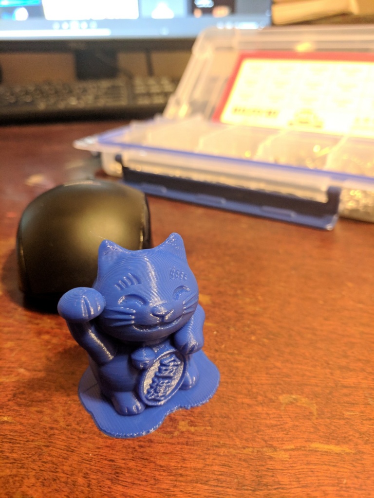
Meow! The gcode for it indicates that it’s printing with a 0.2 mm layer height, which the slicing software I’m using calls “draft” (read: low) quality. And indeed, it did print it pretty dang fast! I honestly didn’t realize that it was low quality because it looked pretty great to me, but I am also new to this.
Part of the draw of the MPDM is that it does “auto leveling”, meaning it figures out where the bed is and what kind of slant it has. Knowing this is pretty vital to getting good quality prints, because otherwise it could jam the extruder tip into the bed (see below) or extrude into the air and not have a solid base, among many other symptoms.
I put auto leveling in quotes up above because if you want to get pedantic, it’s technically not “leveling” at all. The way it levels (assume quotes from now on) is, it has 3 switches under the bed, each in a different corners. It uses the extruder tip itself to go down to the bed until it pokes the bed above each of the switches. How much/where it had to press to activate each switch tells it the height of the bed at those 3 points, giving it enough info to determine the plane of the bed. It then compensates for that when it prints, allowing it to print as if the bed isn’t slanted. So, it’s technically not leveling the bed, but effectively is.
(I actually used to do something similar to this for Electron Beam Lithography, where a VERY slight change in height can completely change the exposure of the resist! There, instead of poking several spots, you can focus in a few spots, and analogously use that info.)
Anyway, I went on to my first actual project, a mount for a TOF sensor. I was using the classic HC-SR04 sonar sensor to determine distance but it turned out to be too inaccurate and gave erratic readings. Searching for something better led me to find the VL53L0X, which is amazing. It uses a tiny chip with a 940 nm laser source to measure the time of flight (TOF) it takes to emit and be bounced back by an obstacle. It also has a very small “cone” compared to the sonar sensor, so you really tend to get the distance of what it’s directly pointing at. It’s hard to believe, it really does give you near mm precision out to about a meter, which it’s advertised up to, but if you look at the Adafruit link, it actually seems to be pretty accurate even farther. The downside is that it’s 10-15 bucks in the US, but can be had from China for ~2-3, and they seem to work just as well.
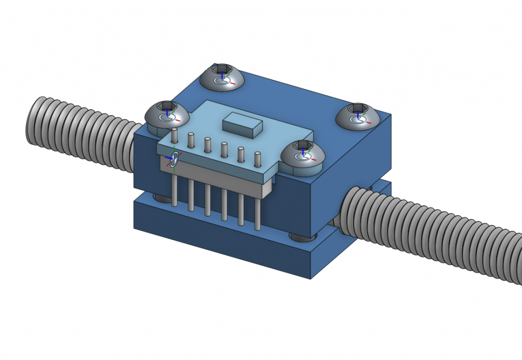
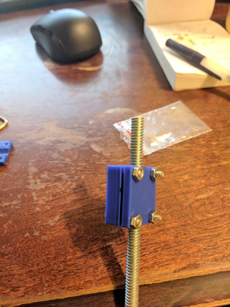
The TOF is being used for another project (more on that soon!), and I needed to mount it to a vertical 1/4″-20 threaded rod, ideally pretty tight. I wanted to make it so it could easily be taken off, be as close to the rod as possible, and have space for the connecting wires.
The first thing I did was whip out the digital calipers, take some measurements of the TOF, and sketch it in Onshape so I could work with respect to it:
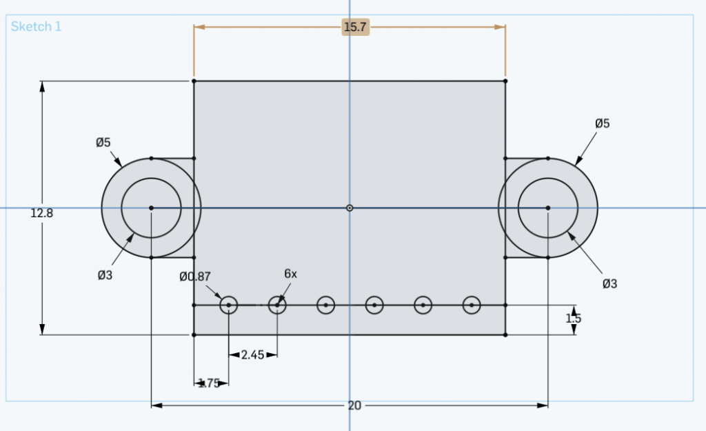
Ahhh, I love Onshape’s constraint system. It makes it really easy to change one measurement and have everything else change to follow it. A few extruding steps lead to:
So the position of the pins makes it a bit tricky to center over the rod, the way I wanted it oriented. You’ll see in a minute. The little nub on the top there is the actual TOF chip, which I added for reference since it’s the functional part.
I decided to do a design with two pieces, a front and back, where they’re clamped around the threaded rod with machine screws:
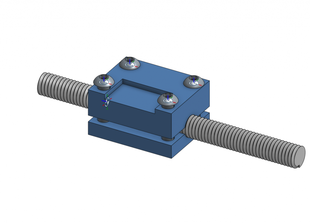
A few notes. This isn’t 100% ideal, because it’s two pieces, when it could probably be one; I probably could’ve had the mount fully attached on one side, with no screws on that side, and then just used the screws on the other side to do the clamping action to tighten it around the rod. However, as I’ll talk about below, holes/negative spaces (like where the rod would go in that design) tend to shrink significantly, so I would’ve had to compensate for that, making the hole big enough for it to slide through but small enough that it could be effectively clamped.
There are also a handful of smaller chips and passive components on the bottom of the TOF, so that’s why I added that lowered area behind where the chip goes. It actually rests on the screw holes parts:
This is also another way this design could be better: ideally, you could take the sensor off without having to take the whole thing off, but you can’t here.
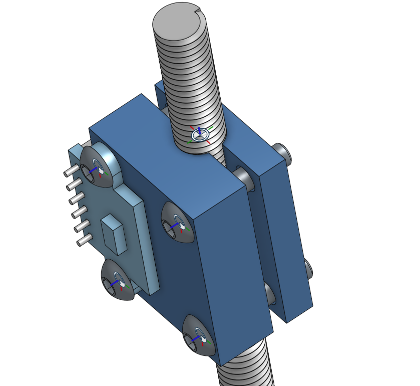
You can also see the challenge of getting it centered over the rod. You definitely couldn’t if it was rotated 90 degrees CW here (the pins/wires would go straight into the rod), and it would be tricky to mount it over the center and not have the screws collide with the rod. There are definitely ways, but this is a pretty easy compromise.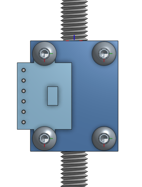
How’d it come out?
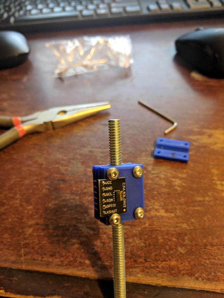
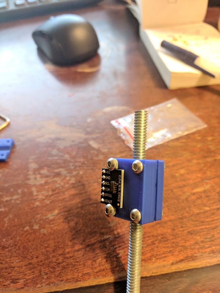
Not too bad! There were actually a couple intermediate struggles, like how I totally forgot that holes tend to shrink when printed, so to specify their diameter as a little larger, so you get what you want. I originally had them set to 3 mm (width of M3 screw), which came out to be 2.2 mm! I then overshot to 4 mm, which came out to be 3.5 mm. Making it 3.6 mm hit the mark perfectly!
There were also some noobie 3D printing mistakes I made. To make a long story short, I was actually printing on a glass plate to begin with, since not having to deal with tape, better adhesion, etc, all sounded pretty good to me. Cat printed great on the glass. So when I went to print this project, I was terrified and thought I broke the printer when, at the beginning of the print, the extruder did a full circle around the perimeter of the print bed, and crashed into the micro binder clips I was holding the glass plate on with. Since the cat gcode came with the printer and the gcode for this was made in the Cura program, I assumed it was some Cura setting. I thought it was the skirt, but it’s actually not (the skirt is a little test perimeter drawn right around the object).
It turns out that Cura throws in some “starting gcode” before the stuff it produces from the actual slicing of the model. You can specify and edit this code, but if you install the MPDM Cura profile like from here, that apparently adds it. Some of it is stuff you definitely want, like using the right units. However, this weird perimeter that was causing the crashing was from the command:
G2 X0 Y55 I-55 J0 E20 F3000;(Draw a priming arc.)
So removing this fixed that problem. The next was that it appeared to be making the extruder tip crash into the bed, which again scared the crap out of me (though I think it’s probably fine as long as it’s pushing it within the range it gets from touching off for the autoleveling). At this point I knew where to look, so I compared the starting gcode from Cura to the one for cat, and noticed that they both actually had the same autoleveling command, (G29 C-0.8 Z0.30). However, it also had (before where the priming arc one above was):
G1 Z0;(Down to printing height.)
Whereas cat didn’t have that, and when it lowered the Z value for the actual printing, it had:
G0 F4800 X0.394 Y-0.895 Z0.300
So it’s pretty clear that if cat was working well, and going down to Z0.3 (the offset value in the autoleveling command), then going to Z0 would obviously cause it to slam the bed. Getting rid of that did the job!
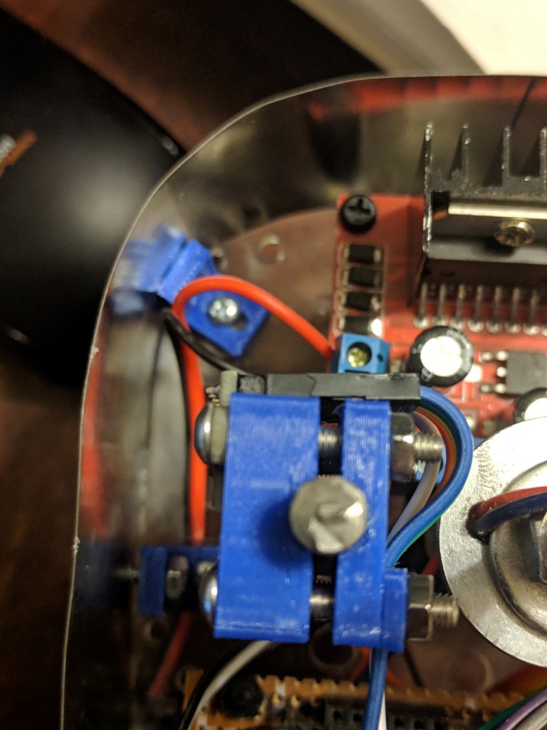
I also found when I started using them that due to how the wires have to bend, they have a tendency to get loose after a few bumps. So, I designed another little part that to clamp the wires so they can’t come loose:
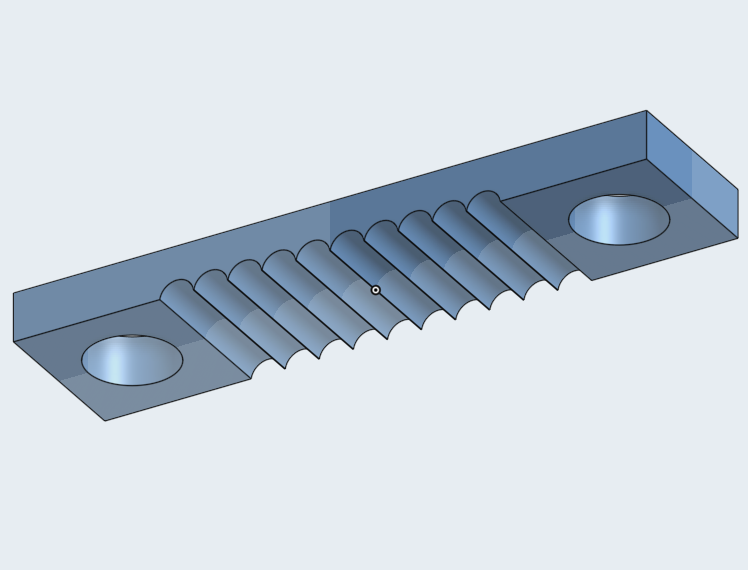
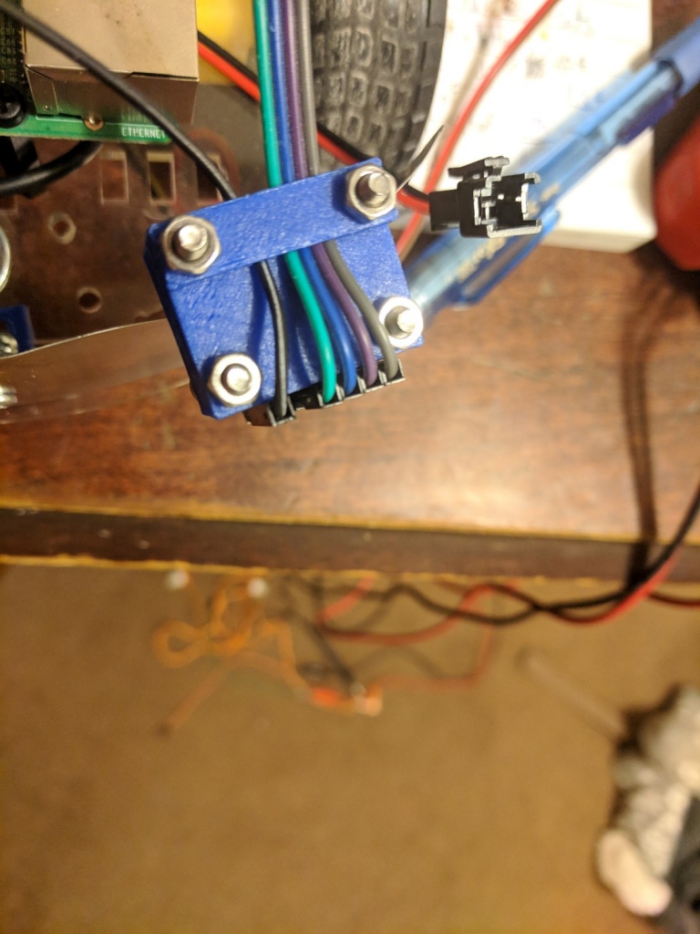
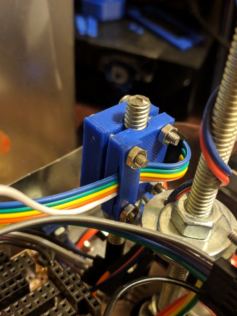
I made it scan just be added to the current design, cause I didn’t wanna redesign the whole thing at the moment, and this works fine. The whole thing is real tight now, and you can tug the wires pretty hard and they won’t come loose.
I also printed this array of little right angle slotted things, for another part of this project:

You can see lots of stringing in between them, which I’ll try to fix. It’s not structurally bad, but it’s definitely annoying. Here they are on the ~~mystery~~ project:
Welp, that’s all! Expect to see lots more of 3D printed stuff.