
This is a follow up to my article “Training a real robot to play Puckworld with reinforcement learning”. In that one, to make it a little punchier, I showed the overview and end results of the project, but left out the insane number of little hurdles and decisions I had to figure out.
So this article will be about those details instead, partly for me to justify the pain, but maybe more charitably to show that for any project with a neat (hopefully?) presentation, there’s probably a harrowing saga of hair-pulling roadblocks behind it. Here, it’s roughly in the order I encountered things. There are lots I’m leaving out too.
How to get the position?
One of the first decisions was how the robot would know its position. In the software puckworld, I think it’s usually just assumed that the robot has its (x, y) coordinates. There are probably tons of ways to go about this. Something I briefly considered was figuring it out externally (like, putting a little tag/bright LED on the robot and getting its location from the Raspberry Pi camera I had looking at the arena). It might be dumb here, but with AI agents they often talk about the environment/agent distinction. Here, the robot is the agent and the arena is the environment, so I wanted to keep them kind of separate — in most real life situations, a robot wouldn’t externally get its position from something that can see it from above, it would have to figure it out from its local position. So, I chose to figure out the position from on board sensors rather than some other method.
How to measure its position? Sonars vs TOFs
With that choice made, I had to actually measure its position. I had never really thought about it before, so I didn’t realize how much measurement info you need to specify a position in a little 2D box. For example, because it has many symmetries, you don’t just need some sort of distance measurement, you also need an absolute direction measurement. In addition, you need to measure several distances from the robot to nearby walls.
I accomplished the direction part with the MPU9250 IMU magnetometer, which is a little MEMS device for about 10 bucks that gives you an absolute compass direction (as well as accelerometers and other cool stuff, but I didn’t use those). More on that later.

For the distances the robot measured, I started by using the classic dinky HC-SR04 sonar modules you’ll get in any cheap robot kit.

They’re about a buck, and honestly, aren’t bad for the price. However… they really start sucking when bouncing off walls at even a slightly non-normal angle, they randomly report really large values, and I think using a few at the same time might have caused them to interfere with each other.
After a bit of searching, I found out about the VL53L0X sensors, which use a tiny IR laser to do range finding.

These things are so damn amazing. They’re also 5-10 bucks each, pricey for a hobby chip, but incredibly accurate and stable, even at pretty oblique angles with the wall. More on them later.
Getting the IMU compass to work
To get the compass to work well, I used a library called RTIMULib2 by Richardstechnotes. As far as I can tell, this is just a labor of love by the guy, and I can’t thank him enough. The library supports tons of variants of the devices and is pretty well documented. I think the MPU 9250 actually does some fancy stuff on board, using the other components (like the gyro/accelerometer) to get more accurate readings, but that’s all contained in the library (or maybe even on chip?).
One thing you have to do is calibrate the compass, or you’ll get weird readings. He offers two types of calibration, a min/max calibration, and a more in depth “ellipsoid fit”. I only did the min/max one to get good enough results, which basically involves rotating the chip in all dimensions so it can figure out the minimum and maximum readings it will see, and scale them appropriately.
Here are the three compass readings, after doing the calibration, turning the robot in 45 degree steps:
 It seems like the third reading must be the one that corresponds to turning around in the plane of the ground, though it’s interesting that there’s a little variance in the 2nd one (maybe some local field?).
Something I don’t have a great answer for is, it seemed like when I’d take the robot up from the basement (where it ran) to my bedroom to fix something, and then bring it back down, the calibration would be totally messed up and I’d have to redo it. It wasn’t powering it off, because I’d frequently do that in the basement, where it wouldn’t need to be reset. It seemed to really have to do with moving it, which makes me wonder if something was being changed on the chip. Weird!
Damn buffers
The readings above looked good, but when I went to actually use the device, I was getting some weird results. It was a bit tricky to figure out, but it turns out that the MPU 9250 fills a buffer with the data it collects. So it’s not an “ask for a reading whenever you want and it’ll give you the current value” thing, it gives you the next value in the buffer (which might be somewhat out of date if it’s moving around).
I didn’t notice this when running the same code above, because it was constantly reading and thus constantly emptying the buffer and getting the most recent readings.
I’m sure there’s a good reason for this design, but it’s pretty annoying here. Luckily, the solution I did was to make a thread for the compass at the beginning of the program so it’s always reading and putting its latest reading into a class variable:
self.compass_read_thread = threading.Thread(
            target=self.compass.readCompassLoop,
            kwargs={'test_time':'forever', },
            daemon=True)
self.compass_read_thread.start()
Then, I just had to call:
def getCompassDirection(self):
  return(self.last_reading)
Where self.last_reading is the last value readCompassLoop() read. Annoying, but it worked.
Getting several TOF sensors to work simultaneously
I needed three of the TOF sensors I mentioned above. I had one pointing straight, one left, and one right. They’re I2C devices, which is usually a pretty nice thing. It means you have an “I2C bus” where all devices you want to communicate with just attach their SDA and SCL pins to the bus, which is attached to the SDA and SCL pins of the master device (in this case, pins 3 and 5 of my Raspberry Pi). Then, they can all function simultaneously, and you talk to a specific one with its I2C address, some hex number.
The I2C address is usually set on the device hardware itself. Sometimes they add a little solder bridge that allows you to change the address a little, so if you have two of the same device (which by default each have address, say, 0x40), you can change the address for one of them so that you can use both.
However, the TOF was a bit different. It didn’t have a hardware change, but you could change it via software. This seems pretty nice, but it turns out you have to do things in a kind of specific order. They even had an example in the library with multiple devices:
GPIO.output(sensor1_shutdown, GPIO.LOW)
GPIO.output(sensor2_shutdown, GPIO.LOW)

# Keep all low for 500 ms or so to make sure they reset
time.sleep(0.50)

# Create one object per VL53L0X passing the address to give to
# each.
tof = VL53L0X.VL53L0X(i2c_address=0x2B)
tof1 = VL53L0X.VL53L0X(i2c_address=0x2D)
tof.open()
tof1.open()

# Set shutdown pin high for the first VL53L0X then
# call to start ranging
GPIO.output(sensor1_shutdown, GPIO.HIGH)
time.sleep(0.50)
tof.start_ranging(VL53L0X.Vl53l0xAccuracyMode.BETTER)

# Set shutdown pin high for the second VL53L0X then
# call to start ranging
GPIO.output(sensor2_shutdown, GPIO.HIGH)
time.sleep(0.50)
tof1.start_ranging(VL53L0X.Vl53l0xAccuracyMode.BETTER)
The TOF has a shutdown pin, where if you set it low (with the RPi), it shuts the device down and it doesn’t communicate on the I2C bus. You can see that in that example, they shut down both TOFs, and then create two TOF objects with different I2C addresses in their constructors while they’re off. However, it seems like setting the addresses in the constructors didn’t work.
Luckily, I figured out a workaround. I found that what works is to shut down all the TOFs, and then for one TOF at a time, create a TOF object with the default address (0x29), set the shutdown pin to high (to turn it on), MANUALLY change the address to something else, and then go to the next one:
print('Creating tof1 at address 0x29')
tof1 = VL53L0X.VL53L0X(i2c_address=0x29)
print('Turning tof1 on')
GPIO.output(sensor1_shutdown, GPIO.HIGH)
time.sleep(0.5)
print('Changing tof1 to address 0x2a')
tof1.change_address(0x2a)
time.sleep(0.5)

print('Creating tof2 at address 0x29')
tof2 = VL53L0X.VL53L0X(i2c_address=0x29)
print('Turning tof2 on')
GPIO.output(sensor2_shutdown, GPIO.HIGH)
time.sleep(0.5)
print('Changing tof2 to address 0x2b')
tof2.change_address(0x2b)
time.sleep(0.5)
When they turn on, they expect to be found at address 0x29, so you need to make sure the ones that are already on have different addresses.
Why does that dang wheel always start turning on boot?
I found that every time I powered up the robot, one wheel would always start turning by default (this is long before any program is running). This was pretty frustrating. The two motors were controlled by 4 RPi GPIO pins. One pin I was using was pin 31 (GPIO 6). Apparently, all pins are set to inputs on boot, which intuitively feels right. But apparently, GPIO pins 0-8 are set to have internal pull-ups, which caused that motor pin to turn on.
Changing it to pin 32/GPIO 12 fixed it.
Wires get loose
This is a dumb little one, but yet another cause of angst. To connect the peripherals and even power, I was just using derpy little Dupont wires:

They work well for most amateur applications, but it turns out that when something moves and crashes into walls literally hundreds of thousands of times, they get loose. Who could have guessed???
Anyway, if you need something a little more secure, at least use JST connectors or similar:

Only certain connections would get loose. Some never did the whole time, some were chronic offenders until I replaced them with JSTs. Womp womp.
Ball wheel vs Caster wheel
Another minor yet important thing. The robot kit I bought came with two motors (each with a wheel attached), and then a caster wheel like this:

Something that frustrated me early on was that this caster wheel caused the robot to have “hysteresis” in the sense that if the caster wheel was straight, and then the robot went left, then right, it would end up in a different position than if it went right, then left. Additionally, if it went straight after turning in a given direction, it would continue going in that direction a little.
This bugged me, so I found what I thought was a really clever solution, a ball caster:

In theory, this should allow it to be omnidirectional, without having any “hysteresis”. It…kind of worked, for a little, but turns out it has two problems. One is that it picked up way more dirt from my basement floor than the caster wheel did. I think the ball directly touches the ball bearings it rides on, so this gummed them up (in contrast, I don’t think the caster wheel above uses bearings on the wheel axle at all). Additionally, while it didn’t matter for the wheel, the ball got scratched up and made it not work with the bearings as well.
The other problem is that I think it’s meant for something like furniture, so it actually needs a bit of weight on it to “engage” and have the ball roll. For something like my robot, even when it was brand new, it ended up just dragging the ball, which really increased drag.
In the end, I realized that it seems like the robot doesn’t actually “care” if it has a bit of hysteresis. There’s such a large imprecise/random element to the whole thing that it doesn’t matter if turns have +- 20 degrees of randomness, or straight moves aren’t perfectly straight. In addition, it seems like a large part of that was the weakness of the old motors — when I moved to the new ones, it seems like their larger torque overwhelmed the wheel’s resistance.
Slip ring: sometimes, just get the right tool for the job
Early on, I had to make a decision about how to power the robot. For obvious reasons, most people elect to power a robot by battery if they can. However, I knew this probably wasn’t an option given what I wanted to do: my back of the envelope calculations told me I’d need on the order of a day of constant action. It would need to power a Raspberry Pi (~500 mA, more on that below), as well as two motors, regulators, and a bunch of peripherals. That’s something you can probably do over a short period with a few LiPo’s, but if we said it’s ~2A for 24h, that’s something like ~50,000 mAh. Maybe batteries like that exist, but not ones that would fit on this dinky robot.
So I realized I’d either have to do lots of recharging batteries (no) or power it continuously. The wire obviously couldn’t just trail behind it, so it had to come from above it, so I built the frame:

But you can probably see that it also can’t just be anchored to the frame, because the robot has to turn, and that would cause it to tangle over long periods. So, I rigged a cheapo little (what I would later come to find was called) slip ring:
It actually worked not completely terribly. But after a while, I was finding that I’d still come back to it after several hours and find that it hadn’t let it rotate enough, the wire was all tangled up, and the robot was on one end, futilely trying to move in a Sisyphean hell. I don’t know why it stopped working, but it seemed hard to get the right balance between having it tight enough that it made constant electrical contact, but loose enough to easily swivel.
The dumb thing is, I knew about slip rings (the concept of them, anyway). A few minutes of googlin’ got me the name, and I immediately found one on amazon. I sighed and reluctantly shelled out the 20 bucks for the beefiest one, and installed it instead:

It worked immediately and perfectly. This drove home for me that sometimes you have to not waste time on bad solutions, if solving that problem isn’t the point of the project, just an impediment.
The sagging wire problem
A related and similarly small-but-crucial problem had to do with the power wire itself. Now that it rotated freely with the slip ring, there was still the question of how to make it so it wouldn’t get in the way of the robot. I had fortunately added a 1/4″ threaded rod to the robot’s middle, about 8″ high, early on, to keep the wire away from the peripherals, but it could still tangle around the rod itself. The wire had to be long enough that the robot could get to the corners of the arena, but not so long that it would sag too low when the robot was at the center of the arena.
An elegant solution would have been to use a coiled/springy wire, like a classic telephone wire:

that would stretch out/coil up as needed. However, the robot isn’t super heavy, so it seemed to me like it might be difficult to find one that would have the right springiness to uncoil when the robot is at the corner, but not restrict it either.
Instead, I went for a hack-y but totally successful workaround. I have a ton of heat shrink tubing, so at the top of the threaded rod where the wire connects to it, I just added a ~4″ section of the widest tubing I had (the blue at the top):
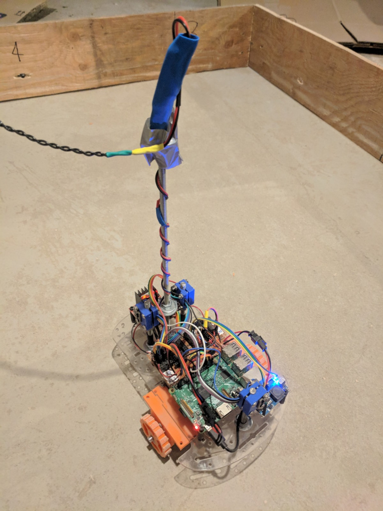
This kept the wire upright and out of the way of the rod when it was in the center, but was weak enough to bend when it was in the corner. Simple and derpy, but perfect here.
The mysterious shutdown
This was perhaps the most frustrating problem of all of them. By about the time when I was starting to have the robot actually learn (i.e., running it for more than a few minutes at a time), I found that it was mysteriously and sporadically shutting down. It would happen after different lengths of time into a run.
I had a debug file I was running constantly anyway (that logged nearly every action/program section), but that gave no results — often, because it must have crashed while it was open, the last entry would be gibberish. At this point I as always running it via ssh, so I worried that maybe just the internet connection was breaking and that was killing the process. I tried other methods, like using nohup and piping to a log file, so it wouldn’t matter if the connection broke, it would still log it. That didn’t illuminate anything; it seemed like it crashed at random places. I believe I also tried screen by this point, which should really not matter if the connection breaks and the screen is detached.
It was pretty clear to me that it must have been some sort of power issue: if my ssh connection/the program was crashing, that means the RPi was turning off, and that’s relatively unlikely to be due to a software problem (compared to the million menial hardware things that can go wrong). If it’s hardware, then it’s probably that the RPi is somehow losing power.
Any guesses?
Here’s a clue: it was actually kind of both hardware and software.
Since it seemed like a power issue, the two most obvious culprits were the power supply (a 12V, 2A) and the 7805 5V regulator I was using to power the RPi. The 7805 can supposedly supply 1.5A, but I measured the current (the total going into the robot) consumed by incrementally adding each part separately and it seemed enough.
The RPi only took ~320 mA. Running a motor test (so RPi plus the two motors) under typical load gave a total of 1.2A. The peripherals took basically nothing.
I considered that the 7805 might be getting too hot, so I added a beefy heat sink, but nothing. I thought that maybe, when under the heaviest load, its output voltage might drop, so I measured that. The lowest it went, at its hottest, was 4.88V, which isn’t ideal, but should still probably power the RPi (it didn’t shut off at this voltage anyway).
To make sure it wasn’t the power supply, I got a new 12V, 5A one. No change. At this point, I was getting pretty desperate and trying things I knew were real long shots. I added smoothing caps across the voltage lines, but given the sporadic working, it was obviously unlikely to be that. My best guess is that in some rare position, the motors became a larger load and drew more current.
I think the clue that probably solved it for me was that I’d only see it when training the robot, and never when just running it directly (I had a little direct_control.py script for controlling it directly from my laptop). I knew it wasn’t like, some bug or error making it freak out (given the debug logs/etc above), but it made me consider that maybe something else was going on, like running pytorch on a dinky Raspberry Pi might be too much for it. Indeed, looking at htop revealed that the CPUs were basically under full load. This is okay, but… I took one more measurement, running just a program that printed numbers in a loop from 0 to whatever. The current instantly shot up to 650 mA!
So I’m not sure what to call this problem exactly, since it was definitely hardware, but also kind of software caused. Of course, the real problem is that I was powering it from a source that was already dangerously close to underpowered, which is obviously silly. I solved it by just using a buck converter which could easily deliver 2-3A and never had the problem again.
Just…don’t use bad motors
Until bafflingly late, I used the crappy motors that came with the robot kit:

To be fair, they did work for a while, but they were incredibly underpowered and generally probably not meant to be used for more than a couple hours of total runtime, let alone dozens of hours in a row, for days on end. Eventually one really crapped out. I ordered more, before reading a tiny bit more and figuring out that I could have really solid geared up motors for ~10 bucks a pop:
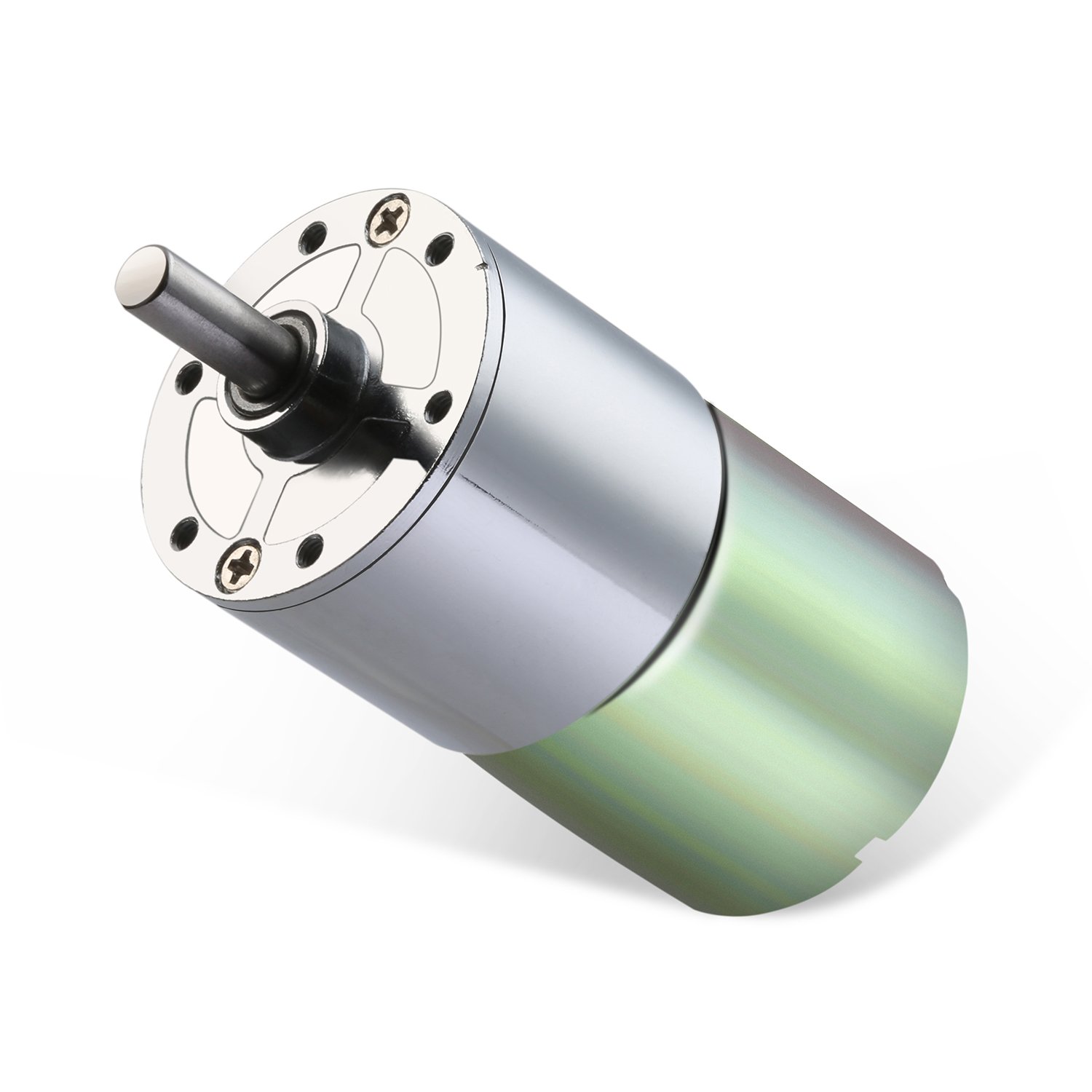
I grabbed them and never looked back. They’re so much more solid and powerful. Any amazon link might die soon, so you can usually find them listed under some word soup like “DC 12V 100RPM Gear Motor High Torque Electric Micro Speed Reduction Geared Motor Centric Output Shaft 37mm Diameter Gearbox” (in the case of this one). One other problem with the original ones is that the wheels they came with were getting pretty stripped down over time, so barely had any tread left. On the flip side, the new motors didn’t have any wheels at all, so that leads me to…
The miracle of 3D printing
I’ll get to them in a minute, but the wheels weren’t actually the first thing I 3D printed for this project. I actually got a 3D printer during the course of this project, and since I knew I was using the TOF’s by that point, my first practical project was building some mounts for them:

Lawdy lawdy, I was doing such janky things to mount things before I got the printer. One of the best things about them is the ability to create the perfect little piece for some really specific job. When I got the new motors, I needed both wheels and mounts for them. The perfect job for a shiny new 3D printer, so…
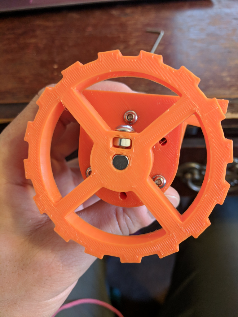
I used a “captured nut” technique to attach the wheel to the axle securely, which worked pretty well. I added a hole in the top, aligned with the trough of the teeth, to be able to tighten it:

To be able to tighten the nut more, I often added a little dab of epoxy after squeezing it in there (so it wouldn’t rotate if I tightened it more).
The wheel went through several iterations too. I had to balance a few things. I was worried that the PLA I print with would be too soft/etc and wear away too quickly on the wheels, but it actually held up pretty well, such that I could get about two full runs (~50 hours) on a pair. Here’s how they look as a progression of use:

So, I wanted to design them so that the treads would stay there even as they wore down, but also make them not take much material, so I could more quickly print replacements. The center part also had to be sturdy enough for the screw/nut thing.
Save save save!
This is one I’m embarrassed took me so long to implement, given how obvious it is in retrospect. Even when I had things fairly ironed out in the end, things can still go wrong and it’s expecting a lot of a robot to run for hundreds of thousands of iterations without any problems. So for a while I was finding that pretty far along runs would get ruined by something small.
The obviously solution was to add a form of “checkpoints” such that every (for example) 1000 iterations, it would save everything it would need to pick up from that point again as if it never stopped. This meant saving its NN parameters, the experience replay buffer, the reward/action/position/etc list, the agent parameters, and the NN optimizer current parameters.
This was also important for practical reasons: my neighbors on the 1st floor (directly above where the robot ran) didn’t seem to mind it during the day, but I could imagine it being creepy/annoying if it was making noises running at night. So this allowed me to stop it in the evening and pick it up again in the morning, for long runs.
And the rest
These are still not all of them, but you probably get the point. I guess if I had to boil down the lessons I learned from this project, they might be:
- Go ahead and try the DIY/cheapo method if it seems reasonable (the slip ring, the sagging solution, cheapo motors, etc), but if it’s obviously holding you back (…the slip ring, motors), just spend a few bucks to fix the problem.
- 3D printing is awesome for projects like this. That bad boy has paid itself back 10x already.
- Doing projects that are meant to run for a short period vs long stretches are VERY different stories. Silly stopgap solutions are fine for short things, but long stretches kind of “test” every facet of the project. If it’s a “long stretch” project, think about what will fail when you do it 500,000 times vs 500 times.
- Something I already knew, but project logs are vital to big things like this. Being able to go back and see what you tried is really useful.
- This won’t really change my behavior in the future, but I think I got a glimpse at how cumbersome projects can get. This was a one person effort, doing something (in the wide scheme of things) pretty small, and it got huge. I can only imagine what the codebase/management process is like for an actual large project.
1 comment
Hi, Which python library did you use to visualize your network?