I recently got a dog!


Her name is Goose, because when we first got her she had a kennel cough, and it sounded exactly like a goose’s honk. She was roughly 9 months old (she’s a rescue, so stuff like dates and the breed are just a guess) when we got her, so she’s not quite a puppy, but still has plenty of recently-puppy energy. Appreciate more pictures of my pup!


APPRECIATE HER.
I mostly work at home, but sometimes when I have to go out for several hours, she gets…rowdy. I don’t know if she has separation anxiety, or is just taking advantage of being unsupervised to be a little demon, but…


It’s pretty hard to train them out of something they did hours ago, so I needed another solution. I wanted to make something that would distract her so her little walnut brain wouldn’t turn to destruction, and a device that periodically feeds her a little seemed like a good candidate. I briefly considered 3D printing a device, but after thinking about it for a bit, it seems like it might actually be kind of hard to rig something up that 1) has a decently sized reservoir of food, 2) only lets out a little at a time, and 3) is mechanically robust. For example, if you look at how the classic gumball machine works, the mechanism for dispensing only a small amount of candy kind of relies on them being a fairly uniform size, being fairly frictionless, and the whole mechanism is metal (i.e., much harder than the candy). So trying to replicate this with plastic and kibble (very friction-y and a bunch of sizes) might be tricky.
Instead, I just decided to mod an automatic fish feeder:
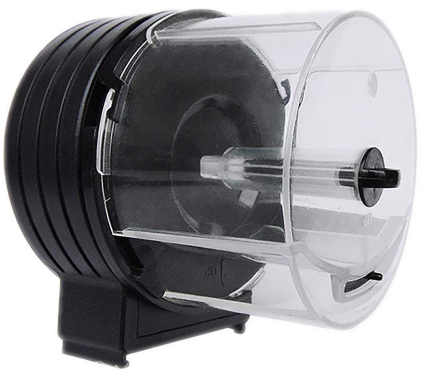
It’s actually a pretty clever mechanism I hadn’t thought of. The food just sits inside a barrel. The barrel has a little window in it that leads to a little “antechamber”, which winds around a little before going fully outside, so when it does one full revolution, a bit of food is able to enter the antechamber and fall out. Because it’s moving and both the window and antechamber are pretty small, only a bit of food is able to fall out. Really clever design without moving parts directly gating the food!
So I got one of these, but because it’s meant for fish, it’s only programmed to feed every 12 or 24 hours. Fortunately, it also has a “manual feed” button you can just press. Typically, pressing a button just means bridging two parts of the circuit on either side of the button, usually connecting something to ground or the circuit’s positive voltage. I opened it up, powered it on, and poked around with my multimeter.


As expected, one side of the button is at 0V, and the other side is at 3.3V. When you press the button, it connects them and triggers the input of some IC. I tested it by poking the 0V side with a wire connected to the positive voltage, and it worked sporadically. I figured it had to do with my timing of poking the wire, and I could work out the precise timing later, but it was only after I screwed the whole thing shut once that I realized that the button press wasn’t pulling the 0V side up to 3.3V, the 0V side was pulling the 3.3V side down! I rewired it slightly and closed the whole thing up.
I broke out 3 wires: ground, 3.3V, and the positive side of the button. The device typically runs on 2 AA batteries, but I thought it’d be nice to instead power it with an external supply since I needed it anyway.


As for the control, I wanted the option to tune the frequency of the food deposits in some time range (~5 minutes or so). Originally I was planning on using a classic 555 timer circuit with a potentiometer. I whipped one up, but only after doing so did I realize that they’re not really meant for such long periods; you start having issues with leakage, tolerances matter a lot, and it’s generally a nightmare, from what I read. So I caved and just used an Arduino mini, and it took about 5 minutes to get it working. To tune the frequency, I used the analog input of it. I knew the concept but had never actually used it. You basically just use the pot as a voltage divider between ground and V+, and the analog input reads the voltage of the pot’s middle pin, and the standard analog input library returns a value from 0 – 2^10 corresponding to voltage values from ground to V+. I’ll definitely be using it again!
For the code, I just used a couple timing functions, where the delay is based on the analog input’s value. In the main loop, it just checks to see if enough time has elapsed, and if it has, it sets the output pin low (i.e., ground) to trigger the feeder. Here’s the simple code:
int sensorPin = A0;    // select the input pin for the potentiometer
int ledPin = 13;      // select the pin for the LED
int outputPin = 12;
int sensorValue = 0;  // variable to store the value coming from the sensor


int max_period_s = 600;
int time_low_ms = 800;
double max_reading = 1023.0;
int loop_delay_ms = 300;
unsigned long previousMillis = millis();

void setup() {
  // declare the ledPin as an OUTPUT:
  pinMode(ledPin, OUTPUT);
  pinMode(outputPin, OUTPUT);

  digitalWrite(ledPin, LOW);
  digitalWrite(outputPin, HIGH);

  Serial.begin(115200);
}

void loop() {
  // read the value from the sensor:
  sensorValue = analogRead(sensorPin);
  double fraction_on = (double) sensorValue/max_reading;
  unsigned long time_high_ms = (1000.0*fraction_on*max_period_s);

  unsigned long currentMillis = millis();
  if ((unsigned long)(currentMillis - previousMillis) >= time_high_ms) {

    digitalWrite(ledPin, HIGH);
    digitalWrite(outputPin, LOW);

    delay(time_low_ms);

    previousMillis = millis();
  }

  digitalWrite(ledPin, LOW);
  digitalWrite(outputPin, HIGH);

  Serial.println("\n");
  Serial.println(sensorValue);
  Serial.println(fraction_on);
  Serial.println(time_high_ms);

  delay(loop_delay_ms);
}
I chose it so the period is from about 0-10 minutes. Here it is in a nice little package:
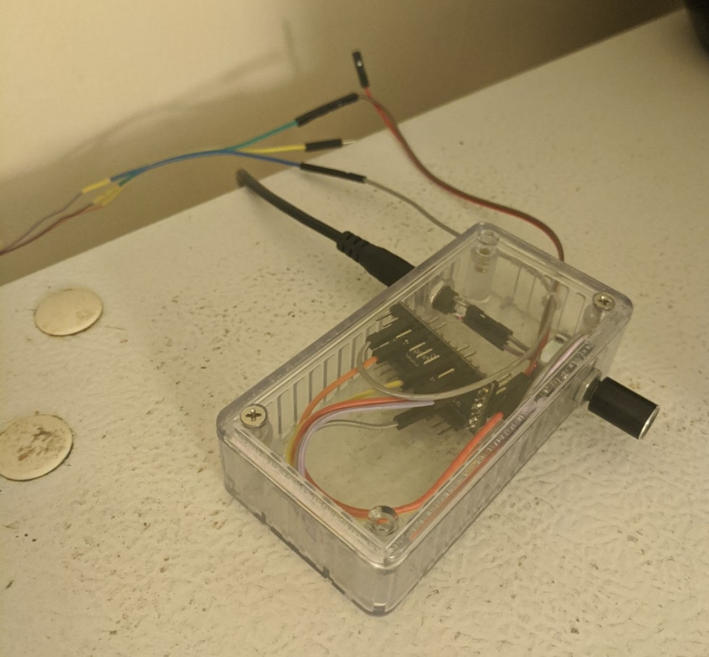
The feeder is built with a nice clamping mechanism, so I put it high up where the hungry rascal can’t just grab it and destroy it:
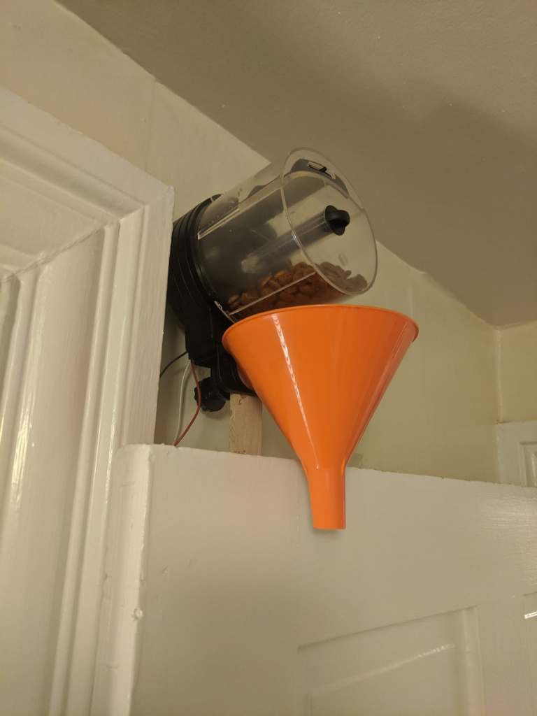
I also used half a funnel to make sure it goes in the right direction. How does it work?


That’s a distracted and less destructive pup! I’ve used it a handful of times so far and she hasn’t destroyed anything since.
A lot of this may seem like overkill, since I’m guessing devices like this already exist. But it’s actually part of a larger plan! In the future, I want to see if she can learn simple puzzles I program. I’ll get a few large buttons she can press, and those can be inputs to the Arduino. I’ll have some type of game programmed so that if she does the right sequence (maybe indicated by some lights?), it’ll trigger it.
There are a few downsides to this setup. The main one is that because of the way the feeder circuit is, to not trigger it, the Arduino trigger pin has to stay high. That’s not a problem for it when it’s running, but it means that its default value, if it’s off, is 0V, which does trigger it. All this means is that I just disconnect the trigger wire before I turn the Arduino off, but it’s a bit annoying. A better solution would be to have the Arduino trigger pin actually control a relay or transistor, which could connect the feeder’s input to V+ by default, and only connect to ground when the Arduino pin goes high. Maybe when I expand it.
See ya!