
DAMN it’s been a while, for both the MPCNC and blog posts in general. But I live!
Back on the horse. I made a post about the MPCNC ages ago, after my friends and I first put it together. And we carved out a few fancy little things!
However, storm clouds were on the horizon. Our workflow was pretty bad: I think we used some crappy online service to make the tool paths from SVG files we found. We tried making something we actually wanted to using Onshape, and a plugin called Kiri:Moto, which kiiiind of worked, but was pretty clunky and limited. Lastly, when we tried to actually carve one of our designs, it was… macabre. This is where our monkey games took a hiatus, but it seemed at a glance like it was doing the design waaay faster and too large, causing the tool to slam into the side, cut through the wood too much and cause smoke, and make the stepper motors skip and make scary noises.
Clearly not everything was alright, but we ended up getting busy with various other things and didn’t get a chance to mess with it again. Until… I grabbed it during our moves to Somerville, and now it’s mine to tinker with again!
The first thing was fixing the basics. There’s a ton I had to do so I put that boring stuff at the bottom, and the more viewable stuff first.
Fancy case!
I wanted to build a case for a few reasons. First, it really cuts down on the noise. Second, the dust from cutting gets EVERYWHERE, so it’s way easier to clean up if contained. Lastly, not that I have to worry much about it here, but it offers protection from any little bits that might fly off.
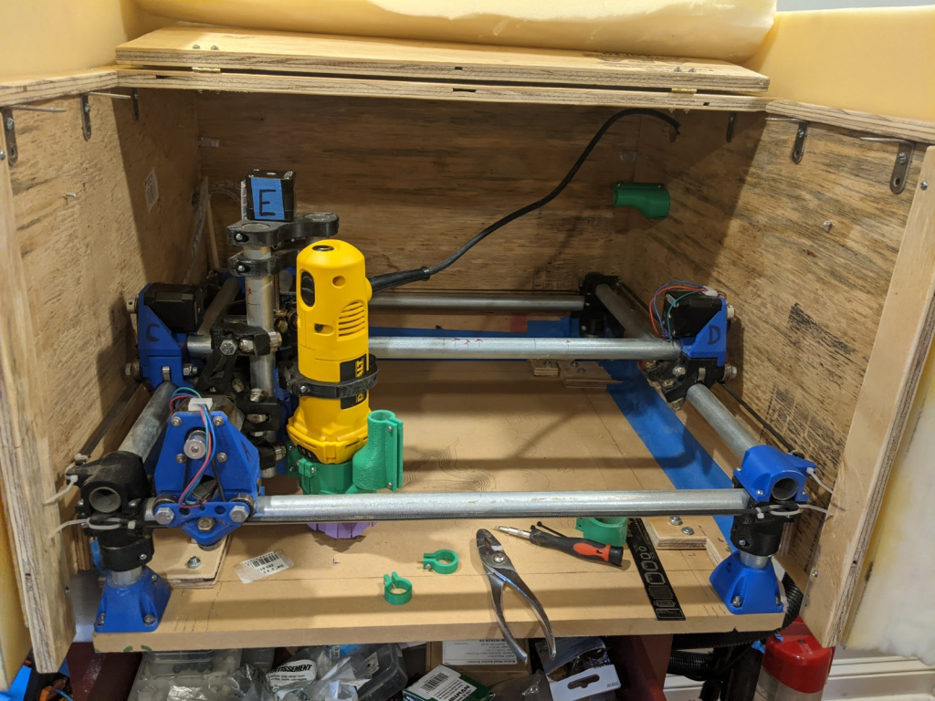
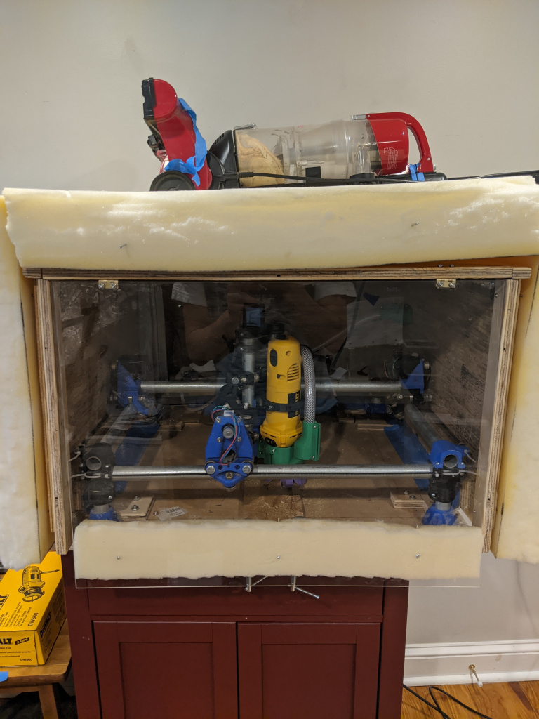
I found some spare plywood, about 1/2″ thick, and put it together with some brackets. Check it out!
You can see that I made the top have a hinge, so I can fold it back for when I need to get in there to fix something.
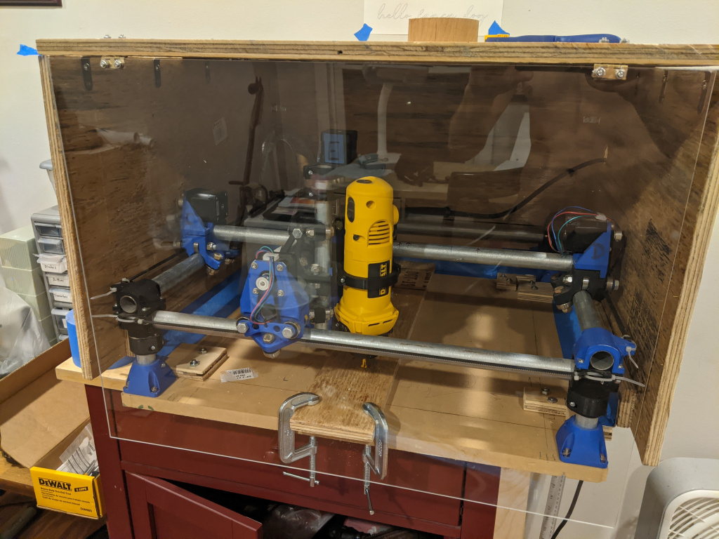
I also bought a plexiglass sheet, that acts as a kind of window. If I’m not trying my hardest to quiet it, it’s nice to be able to see what it’s doing in there:
Since the panels don’t connect fully at the corners, I just put some taping connecting them, which works well to keep the dust out!
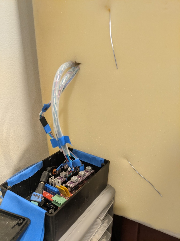
Lastly, I got a free foam mattress off Craigslist, as well as a few other foam sheets I found, and put them on all sides. This REALLY cuts down on the noise. To attach them, I just drilled some small holes in the box, and then pushed some armature wire through the foam. I also had to cut a few bigger holes to feed through the electronics, power, etc:
Vacuum system!
I also found a working vacuum cleaner on the street, and thought that it’d be cool to set up a vacuum system to clean up the dust while it mills!
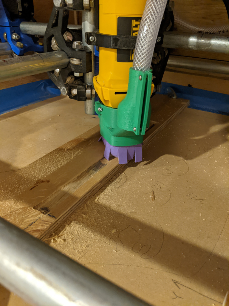
I found this design for a dust shoe mount, which I 3D printed. It might be a little hard to tell from those pics, but you basically attach the hose to the top and it funnels the vacuum down to closer to the cutting bit:
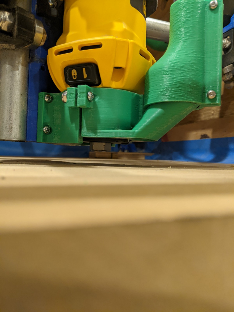
The really cool part though, is that it uses some inset magnets to attach the “dust skirt”:
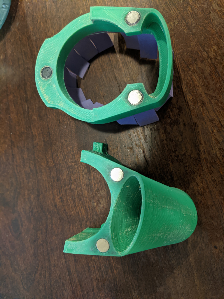
This allows the skirt to snap on to the mount like so:
It’s really nicely designed. Once it’s connected, it’s definitely not going to fall off by accident, but it can be easily put on and taken off, and if it crashed into something while moving around, I think it would knock it off rather than breaking anything.
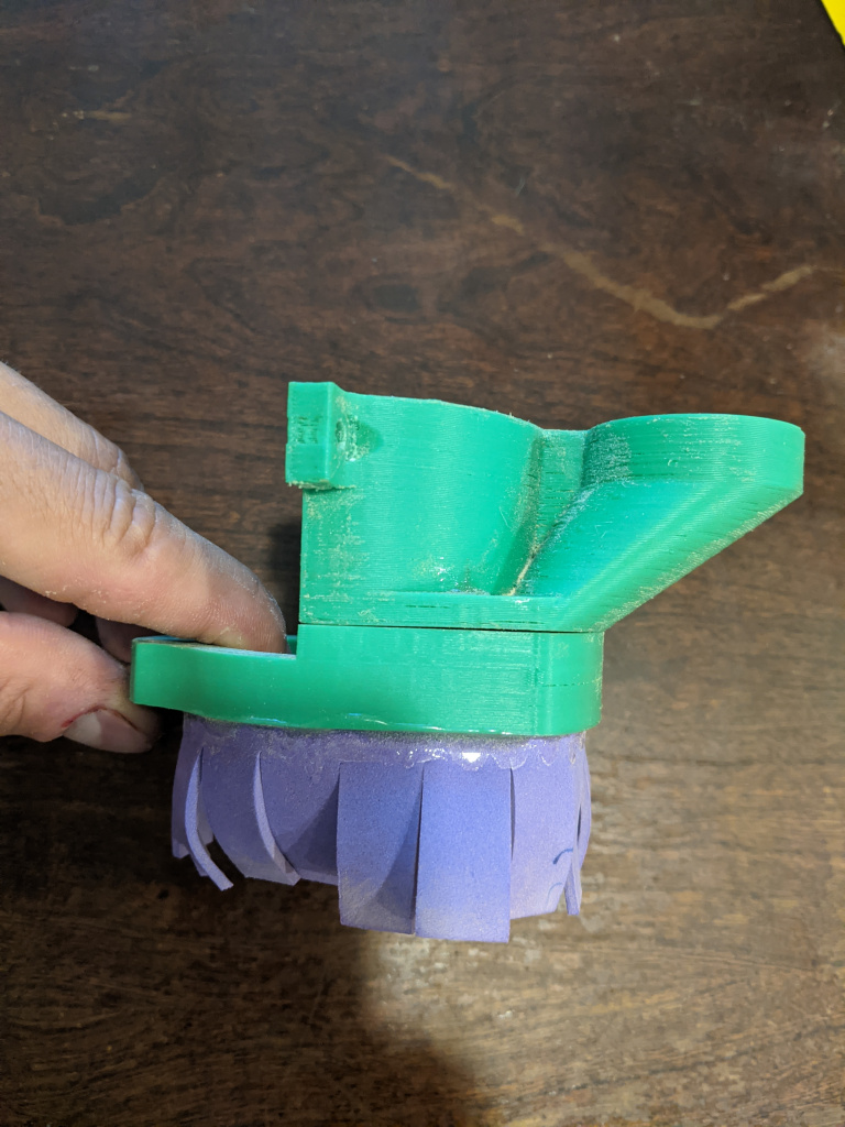
I made the skirt out of just this thin foam sheet I bought online. It has the perfect level of springiness, to not have any effect on the Z direction when it’s going down to cut something, but make enough of an enclosure to keep the dust in (and probably provide a bit better vacuum).
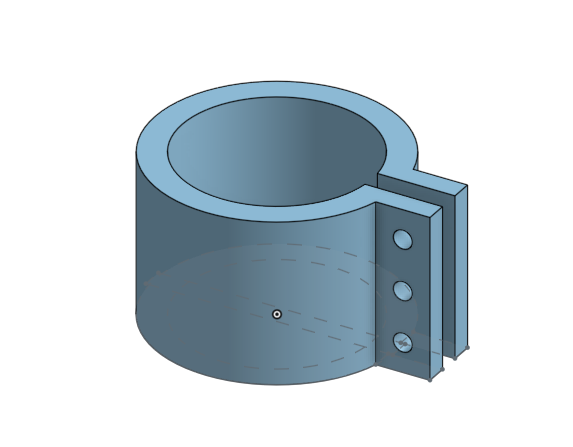
I could’ve chosen to connect the hose that came with the vacuum (1.25″ diameter) directly to the vacuum mount, and I designed a connector to do that:
However, the tube is pretty heavy/stiff, and I have limited real estate inside the box, so I was worried it would either cause the whole CNC gantry to torque a bit too much, or mess up the movement because of the hose pressing against the box. Instead I opted for a thinner tube I bought, which means I had to design a different connector. I made this one in Onshape, which let me make that really nice smooth tapering shape:
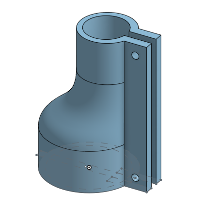
You can see a pic of the printed one above. It works pretty well!
Attaching the tube is actually kind of tricky. It needs to have enough flexibility to not be stiff and hamper movement, but it also can’t be so floppy that it droops down and gets caught in something. I ended up loosely zip tying it to the Dewalt’s cord, which seems to mostly work:
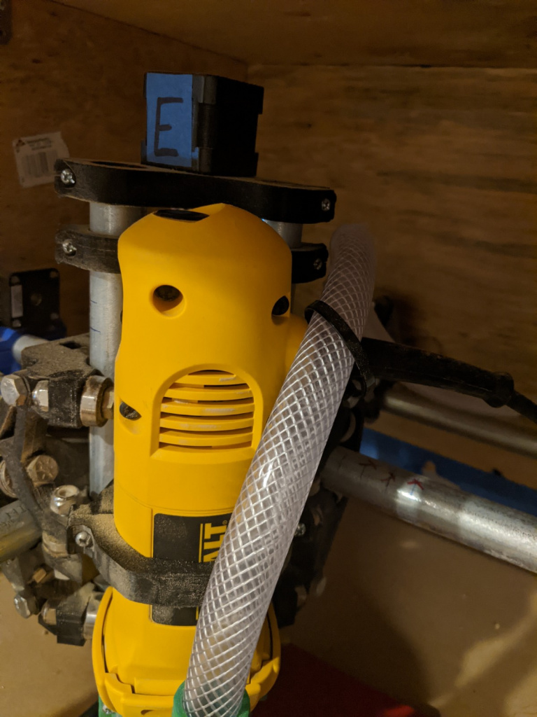
However, I think I’ve read that you really shouldn’t be attaching anything like this, because it can still mess up the stability badly.
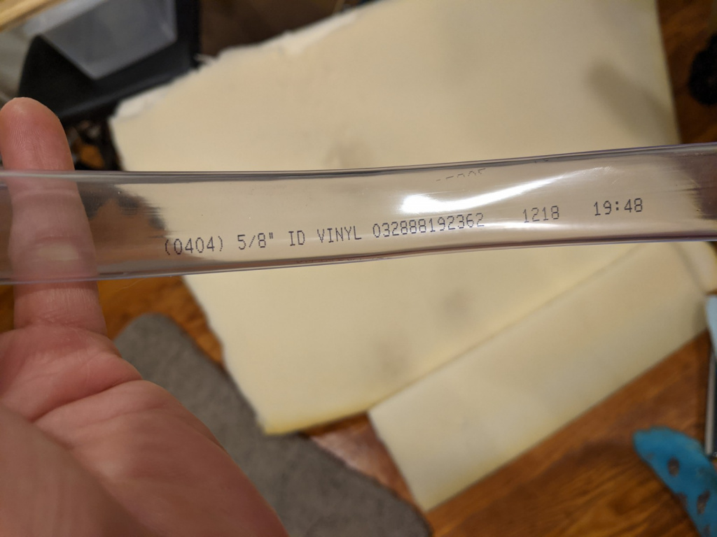
I originally tried using this clear vinyl tube, but I found that it wouldn’t really hold shape. It was slightly flattened, and the vacuum would make it more so. I tried some things like heating it up to make it flexible ad reshape it, but… it didn’t really work. I ended up getting some tube with a weave in it, like you see above, which works much better.
I drilled a hole in the side of the box to stick the vacuum hose in, through the foam…
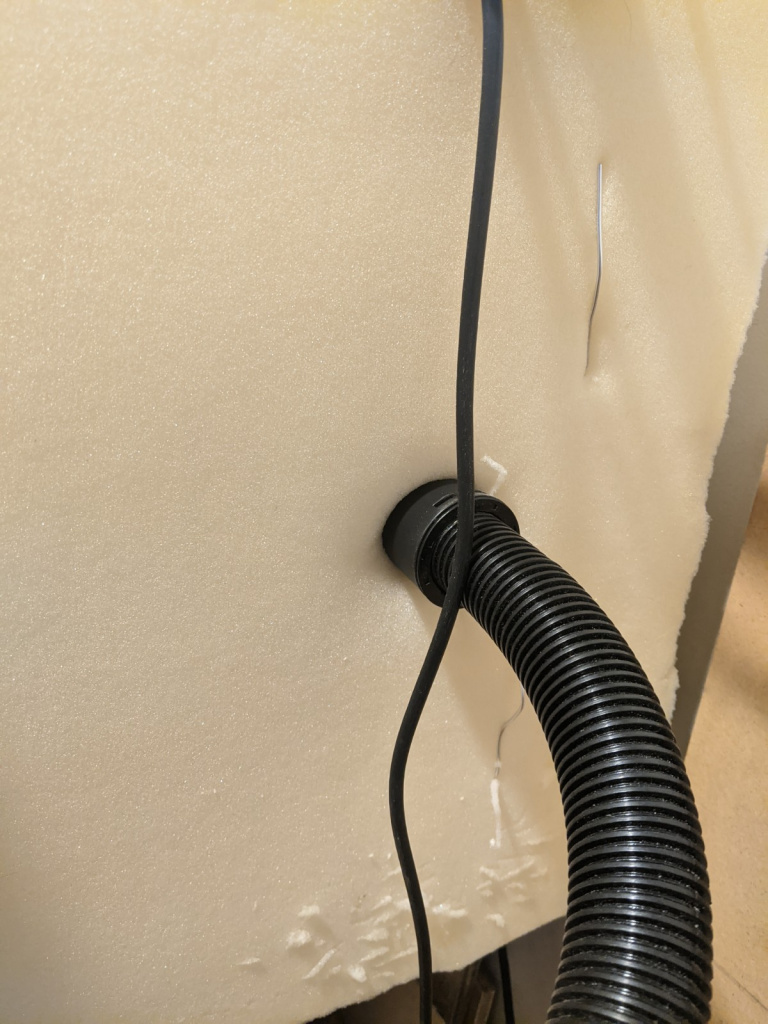
…and on the inside:
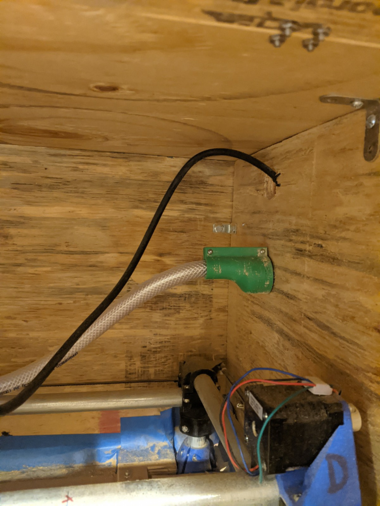
(you can see that I used the same attachment from the mount to tube, to connect tube to vacuum hose.)
You can actually see the best view of the whole “system” (being charitable :P) here:
Lastly, here it is in action. It might be a bit hard to tell, but if you look at the path it has carved so far, there’s pretty clearly less dust. Hurrah!
Rails!
You can only get so far taping your raw stock down, or clamping them to the base 😛 the much more pro thing to do is to get this type of rail:
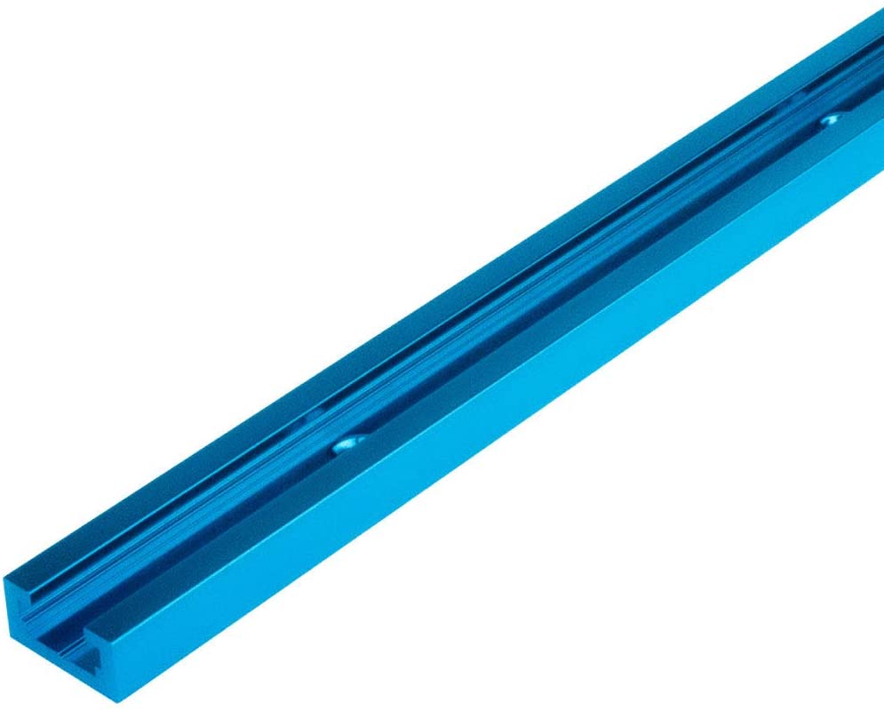
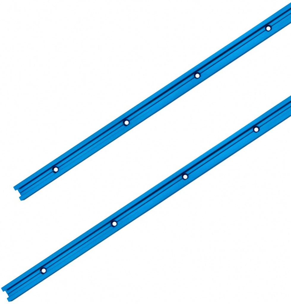
Then, you inset it in the base, so that it doesn’t stick out at all, and then you screw them into the base so they’ll be firm (in the holes you can see above). Then, those slots allow you to slide in some pretty handy bolts.
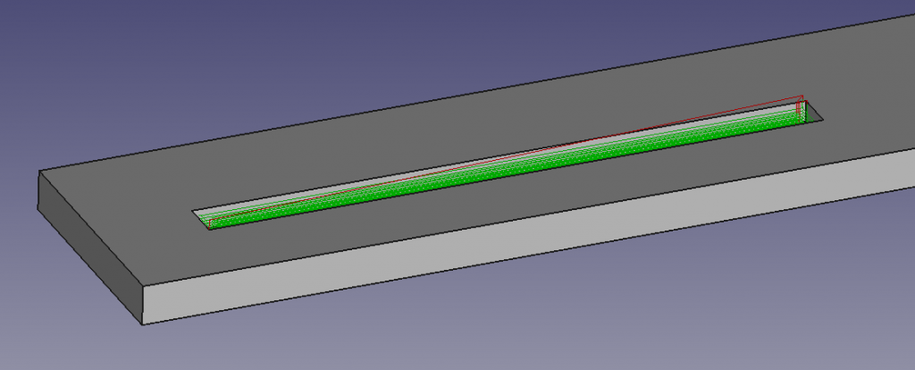
To cut out the rail slots, I designed them in FreeCAD:
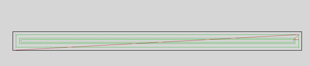
Here’s a top view. You can see I did the “spiral” cutout pattern.
One reason I chose this is that FreeCAD has the option for “dressups”, which you can see here in this closeup:
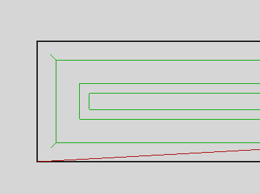
If you’re cutting out something with corners, you’ll never be able to fully cut out the corner with a round bit. Dogbone dressups (the type used here) let you account for this. The little spur you see there is where it’ll cut a little extra out, so the rectangular rail should fit in (obviously it’s now cutting out a little more than you need, but still preferable).
Here are the rail slots from a test run:
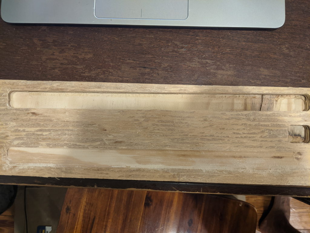
I was worried to actually pull the trigger and do it with the real base, but finally I had to! Here’s the first one:
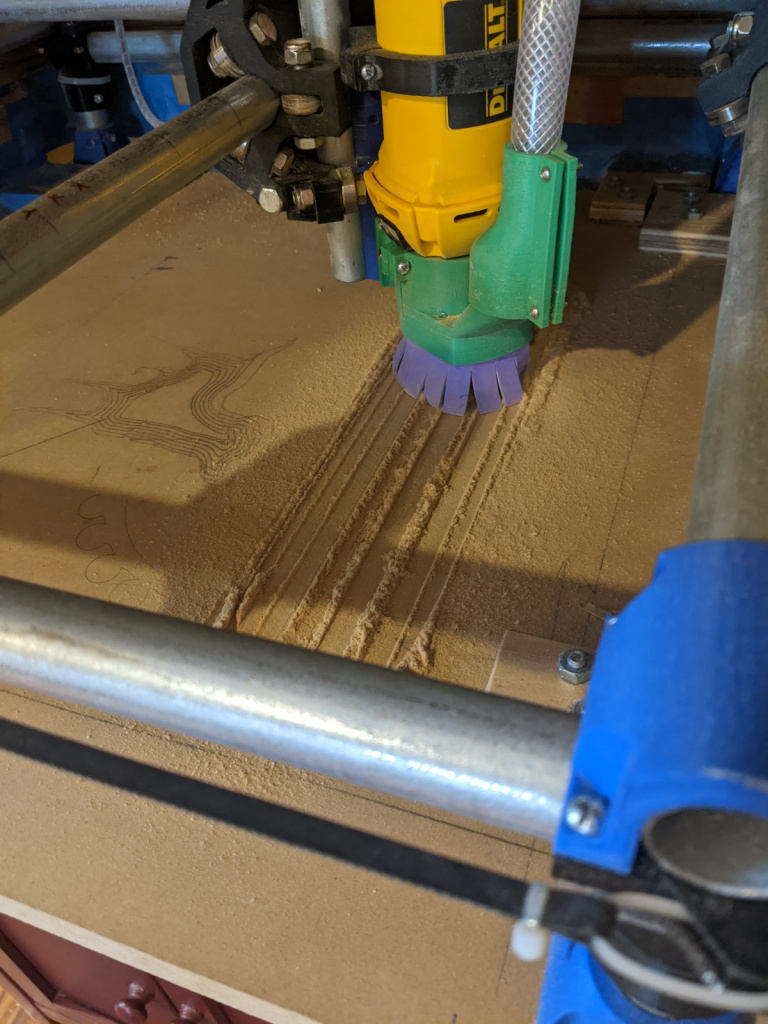
I was kind of confused…is the vacuum that bad?
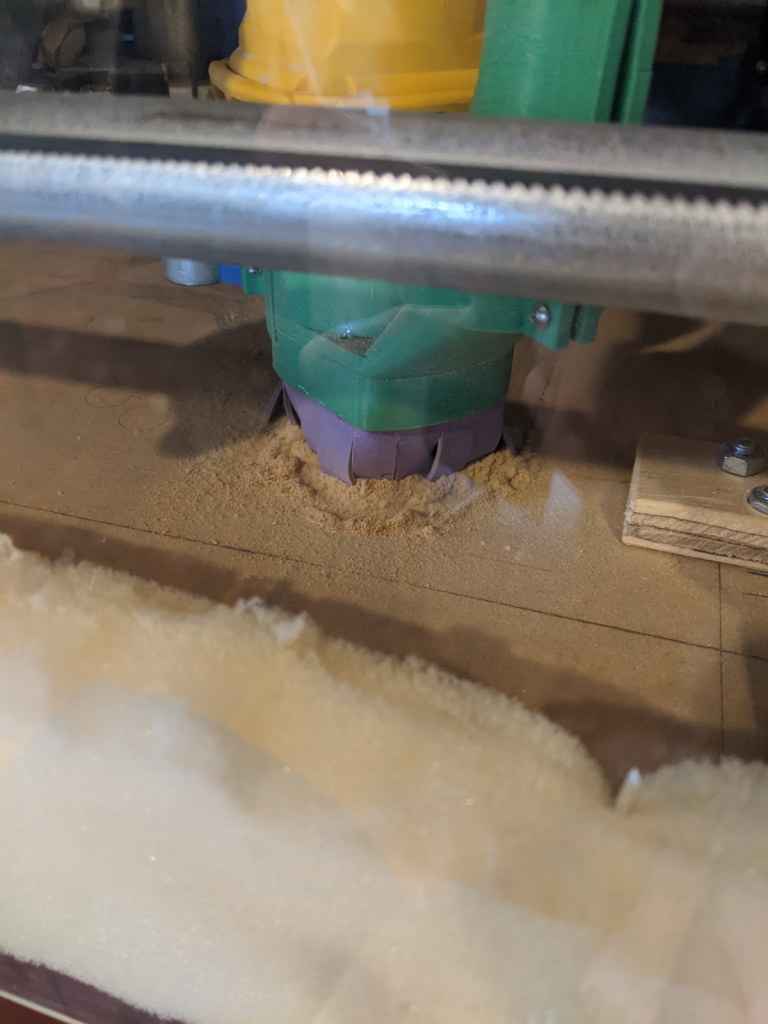
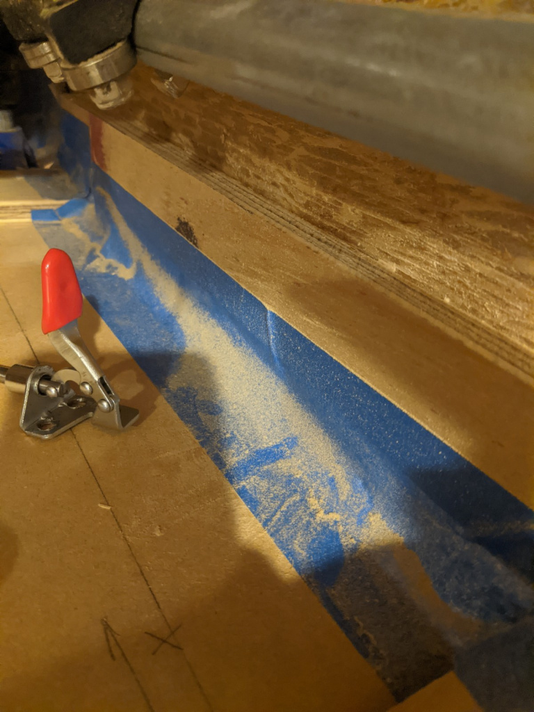
Nope! Something had clogged it. Here’s the second slot after clearing the vacuum, and you can see how much less dust there is:
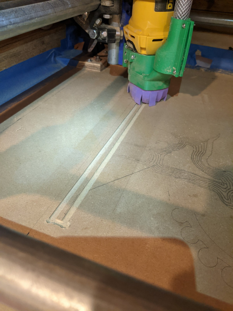
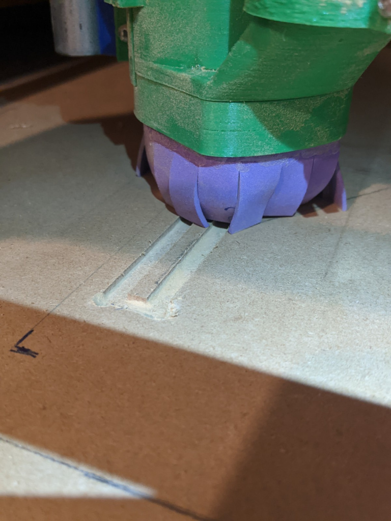
DAMN that’s a clean milling path.
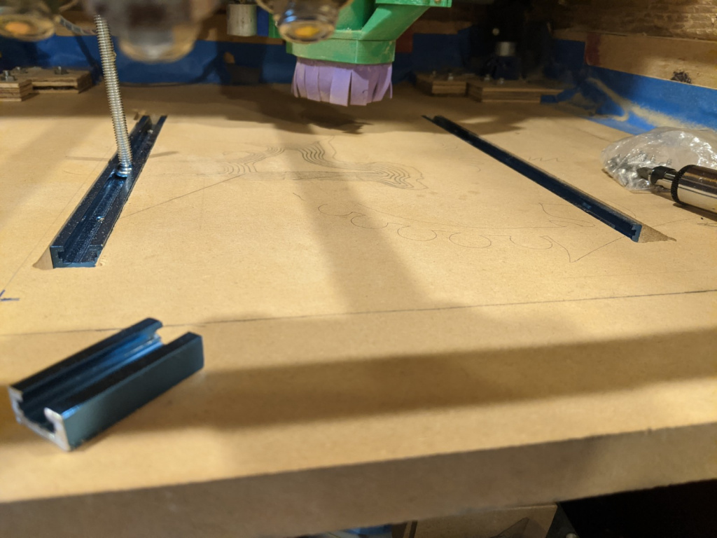
Both of the rails installed:
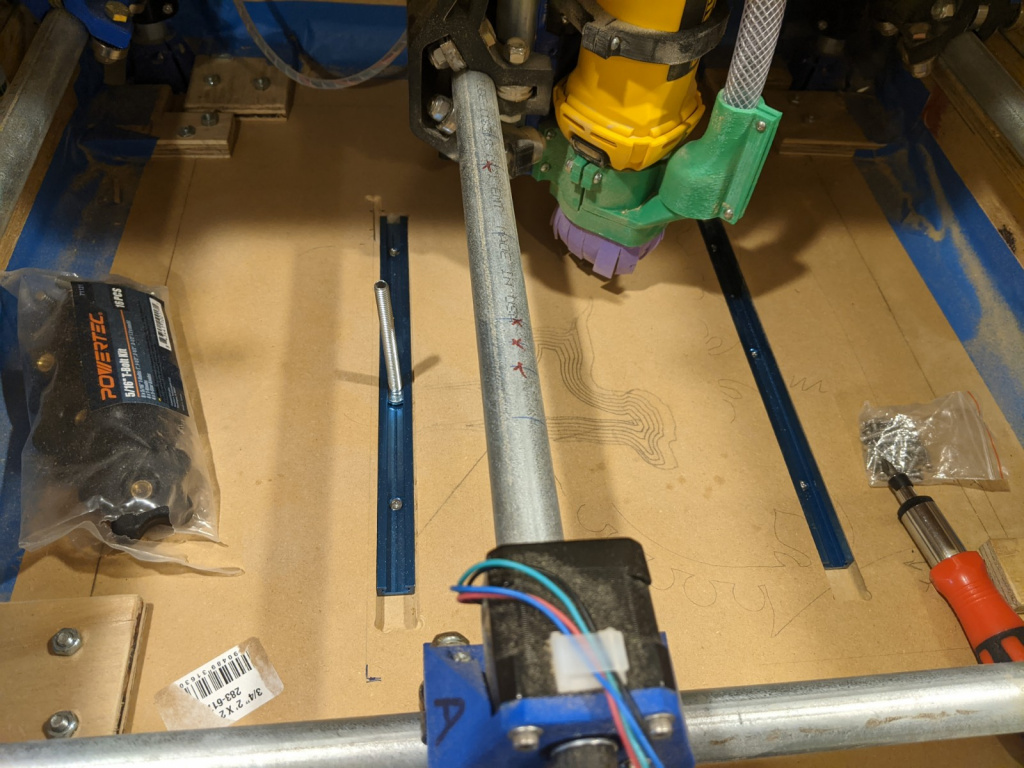
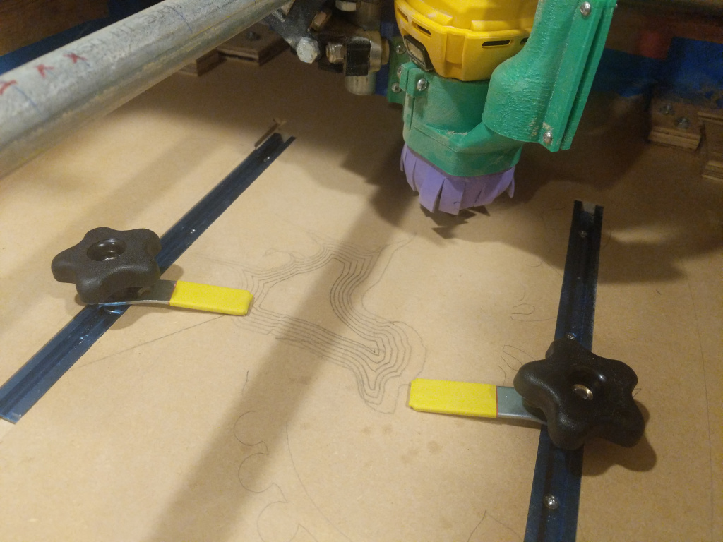
And here it is with a couple clamps in. I basically just used some spare flat bracket things, and covered them in heat shrink tubing.
Taking it for a spin!
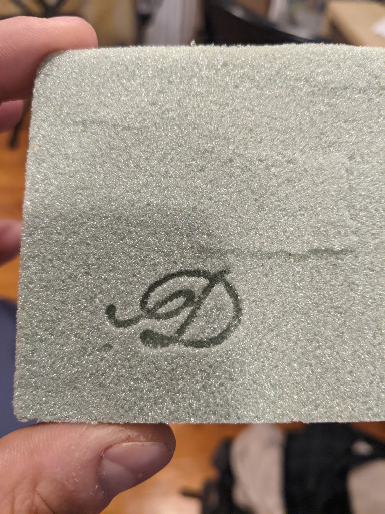
A tip I’ve seen all the pros say, is to, if size permits, test your cut on a piece of lightweight foam first. You know that (usually green) foam you’d see at Michael’s when you were a kid, and even though you knew it was wrong, it was really satisfying to press your fingers into because it would instantly compact it? Yeah, that’s what you want for this. It’s soft enough that even if your program goes totally haywire, it probably won’t break your bit, since you could probably drag it through that foam if the bit wasn’t even spinning.
Sample D:
Run, using plywood spraypainted red, for nice contrast when you mill it out:
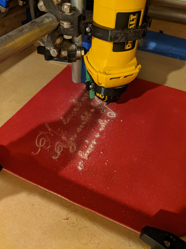
You can see that with this cheapo plywood, it actually splinters a little too much, making it so features that are too close to each other rip out, and you lose detail. Next, I tried this MDF stuff I had sitting around:
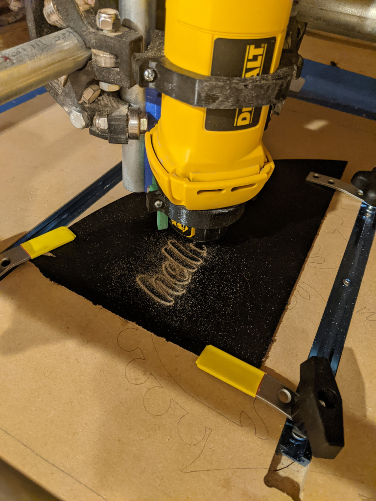
muuuuuuch cleaner:
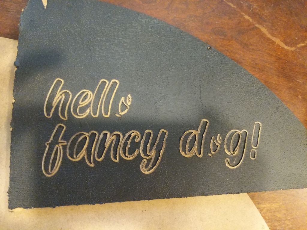
In this case, I actually just rolled on some acrylic paint with a latex stamp roller, so any lost detail is from that paint being too thick and not fully cutting around the edges. But the wood itself cut way cleaner. Also, I don’t know why FreeCAD didn’t include the outside of the “O’s” in the path job? Weird.
The boring nitty gritty
One of the first things I had to fix was the steps/mm setting in the firmware. Back when we used it before, we tried doing some design with real dimensions (as in, we expected it to be X mm long), and were terrified when it ended up trying to do the design, but 2x or 4x bigger, and crashed into the side. So clearly our dimensions and movement were off, and that was the first to fix. The problem is that there’s a setting, the steps/mm, that determines how many stepper motor steps need to be taken to move it a millimeter. So if that setting’s off, you’ll move more or less than you want.
There are probably smarter ways to do this, but here’s a dumb way that works pretty well: you give the command to move 100 mm in the X direction, and measure the distance it actually went. If instead it goes 137 mm, then you know your steps/mm is off by a factor of (100/137) (i.e., you should actually take less steps to get the same distance). That works pretty well!
The next little hassle was the Marlin firmware. I have a RAMPS 1.4 board, and apparently it’s easy to use Marlin for that, even though Marlin is a weird version of gcode.
The next annoying thing was the FreeCAD postprocessor. When you create an object in FreeCAD, you have to actually create a “job” that determines how the object will be cut out of the material you’re doing. Then, to do this job with the CNC, you have to output gcode. There are actually different types of gcode, so if you’re using a specific flavor (I’m using Marlin), you have to make sure it’s outputting that type. That’s the job of the “postprocessor” (PP). There are a bunch of ones available, but unfortunately it doesn’t ship with the Marlin PP.
Luckily, this guy wrote one. It’s really nice of him to share it, but there are at least 2 pretty bad bugs I found.
First, he’s doing some weird math in there, where it moves the Z axis for some reason. I have no idea why, but it’s very important where your coordinates are with respect to! Typically, you say Z is the up/down direction, and typically you also say that the top surface of your stock material is Z = 0, and as it mills away, it’s going into negative Z. You usually start by placing the tip of your bit at the surface, and the program proceeds assuming that. So you can imagine that it could be pretty bad if you thought you were at Z = 0 when in fact it’s Z = 3 or something!
The other one was REAL nasty. It’s honestly one of the harder to diagnose bugs I’ve seen in a while. I won’t drag you through the whole process, but to make a long story short: a simple job I was doing was just halting on what seemed to be a normal command. After trying a million things (including the same command by itself, outside of a program, successfully), it turned out it was… that the postprocessor was adding a bunch of digits of precision to the coordinates of the command. So it was doing something like:
G2 I5.23282 J8.2320002 X8.4400242 Y2.0000284 Z48.992142aaaand it turns out there’s a limit of ~53 characters or something, per gcode line. So despite that being a perfectly valid command otherwise (and indeed if you just remove a few digits from each number it works), it would break the program. Truly hard to figure out, because it would only ever be slightly over the limit when it was. Luckily, there was a built in --precision argument that lets you set that, but its default setting still made me pull my hair out for days.
Next steps
Oh boy, do I have plans!
First, I’ve already designed and made a…novel attachment for it. But I’ll save that for a future post!
There’s a lot more tedious stuff to do. It’s 98% of the way there in terms of working, but it’s not fully square/level yet, which will hurt for precise stuff.
I’d like to try milling out circuit boards at some point! I’ve done the acid etching method in the past, but it’d sure be nice to just pop in a blank and not have to deal with printers and chemicals.
I have a couple other ideas. First, I think it’s a fairly common thing to paint the top layer some color, and then engrave a pattern to reveal the wood color below, for nice contrast. But I’d like to try a multi layer version of this, where I’d do layers of something like: paint color 1, thick laquer, paint color 2, thick lacquer, paint color 3, etc. Then, by engraving to various depths, I should be able to get a cool multi color, multi depth cut.
See ya next time!